
NovaStar MRV412-N Receiving Card: Specs, Firmware and Setup Guide
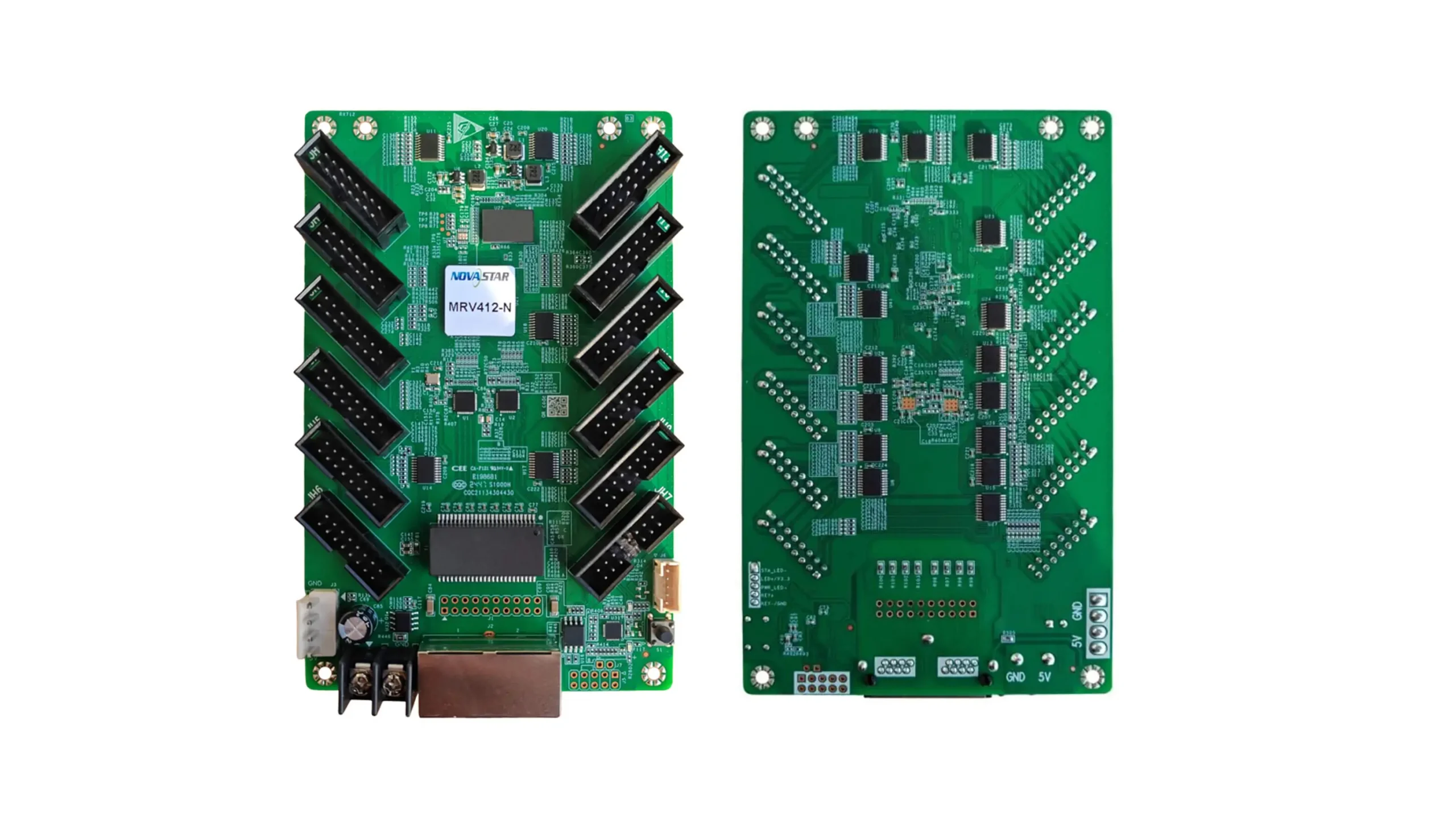
The NovaStar MRV412-N receiving card connects a compatible LED display controller to the modules inside a cabinet. Its 12 HUB75E connectors provide up to 24 parallel RGB data groups. With an 8-bit video source at 60 Hz, the specified maximum is 512 × 512 pixels for PWM driver ICs or 512 × 384 pixels for common driver ICs. The driver type matters: 512 × 512 is not a universal capacity for every module.
This guide explains how to select, configure, and troubleshoot the NovaStar MRV412-N receiving card, with particular attention to firmware, cabinet configuration files, and replacement planning. Whether you are maintaining one cabinet or specifying a complete LED wall, begin with the exact board label, module driver IC, scan mode, and controller model. Those details determine which files and settings your installation needs.
Technical reference: NovaStar’s MRV412-N Receiving Card Specifications V1.0.3, dated May 20, 2025, and its NovaLCT configuration documentation. Document versions, software versions, and receiving-card firmware versions are different identifiers. The installation examples below are planning guidance; confirm the final module and controller combination before ordering or changing a working screen.
1. What Is the NovaStar MRV412-N Receiving Card?
The NovaStar MRV412-N receiving card is the cabinet-level part of the control system. A video source feeds a compatible sending device, which distributes display data to receiving cards. Each receiver then supplies the signals needed by its connected LED modules. A receiver does not replace the sending controller, video processor, or cabinet power supply.
01. Identify the exact model before choosing files
Searches such as “MRV412N,” “MRV 412-N,” and “NovaStar receiver card” may lead to this product. However, MRV412 and MRV412-N are distinct model names. Do not assume firmware, cabinet settings, or replacement compatibility merely because the numbers look similar. Photograph the board label and record the installed program version before requesting support.
For an existing screen, collect one working cabinet’s module label and wiring photograph as well. Pixel pitch alone does not identify the electronics: two P2.5 modules can use different drivers, scanning arrangements, and data routing. A technically correct replacement begins with those differences, rather than a connector-count match alone.
02. Select the receiver around the cabinet
The NovaStar MRV412-N receiving card can be considered for indoor, outdoor, fixed, or rental cabinets when the electrical and control requirements match. The cabinet supplies environmental protection and mechanical support. The receiver’s operating temperature range does not make the bare circuit board weatherproof. For module selection, consult our LED display module options and request the corresponding electrical specifications.
2. NovaStar MRV412-N Specifications and Key Features
01. Specifications that affect installation
Use the following NovaStar MRV412-N receiving card specifications as a starting checklist. Loading limits describe the stated source conditions, while electrical ratings apply to the card itself. LED modules require a separate power calculation.
| Item | Specified value | Installation implication |
|---|---|---|
| PWM driver load | 512 × 512 at 60 Hz; 8-bit source | 262,144 pixels under the stated conditions |
| Common driver load | 512 × 384 at 60 Hz; 8-bit source | 196,608 pixels; check driver identity first |
| Module outputs | 12 HUB75E; up to 24 RGB groups | Verify pin assignments and group routing |
| Input supply | DC 3.8–5.5 V | Measure at the receiver under load |
| Rated card consumption | 0.5 A; 2.5 W | Exclude module power from this figure |
| Operating environment | −20 to +70°C; 10–90% RH, non-condensing | Manage cabinet heat and moisture |
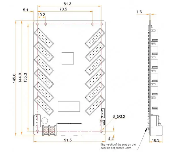
| Dimensions and mass | 145.6 × 91.5 × 19.3 mm; 96 g | Check mounting clearance and cable bends |
Source: NovaStar MRV412-N specification V1.0.3, electrical and physical specifications. Obtain the structural drawing for drilling or enclosure production rather than scaling a product photograph.
02. Image quality features in practical use
The NovaStar MRV412-N receiving card supports calibration and image adjustments, but results depend on the complete screen. Calibration needs suitable measurement data; it does not automatically repair a damaged LED or a poorly seated module. Before adjusting colors, inspect the mechanical joints and establish consistent brightness and viewing conditions.
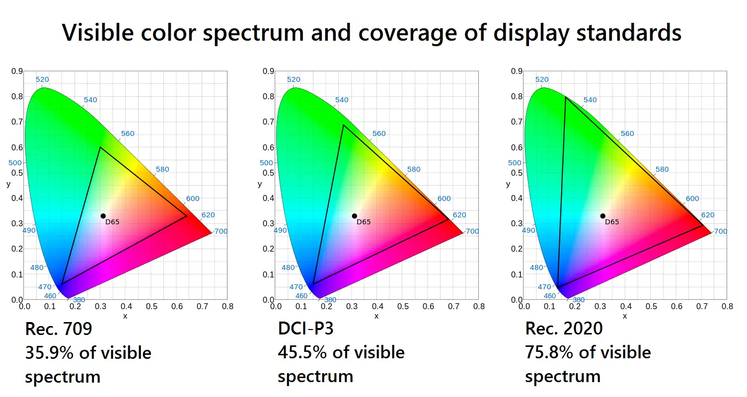
Grayscale performance is especially visible in dark gradients, faces, and low-brightness operation. Evaluate those scenes at the intended operating brightness rather than judging only a full-white test. Color-management settings should match the content workflow and the LED panel’s capabilities; selecting a wider target gamut does not physically expand the LEDs’ native color gamut.
For cameras, test the actual camera, shutter settings, content frame rate, and display configuration together. Source frame rate and LED refresh rate describe different processes. A 60 Hz loading specification does not establish the final LED refresh rate or guarantee that every camera will record without bands.
03. Plan monitoring and recovery
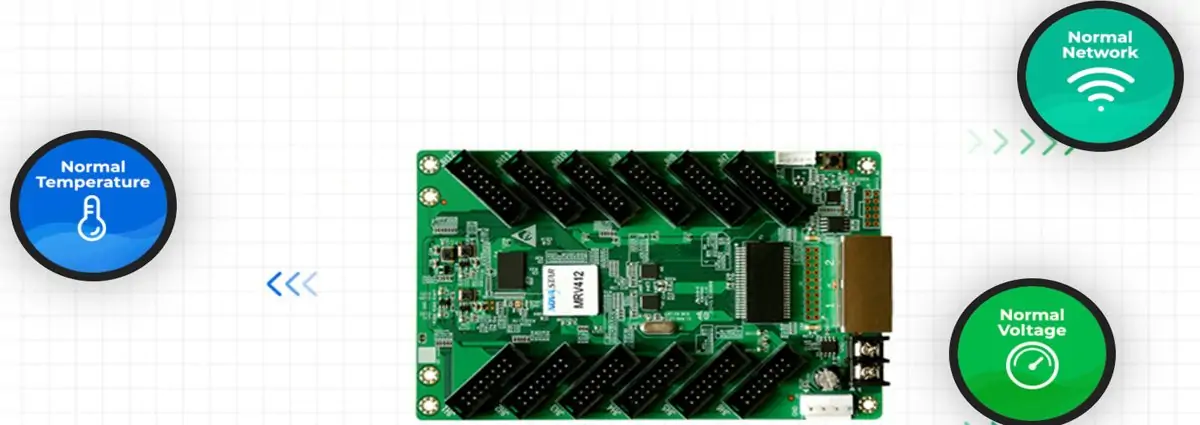
The NovaStar MRV412-N receiving card supports monitoring and backup functions within a compatible control system. During commissioning, record normal readings and cable connections so later changes have a useful baseline. A temperature reading should be interpreted alongside cabinet ventilation, ambient conditions, and operating brightness rather than as an isolated number.
Keep a written distinction between signal redundancy and spare hardware. A backup cable path cannot replace a failed power supply, damaged module, or mechanically broken connector. Similarly, restoring factory parameters may recover a stored configuration but should not be assumed to reproduce every later project adjustment. Make the tested commissioning archive the reference for service work.
For rental inventory, label cabinets and spares by compatible module and configuration group. After repair, compare the cabinet against its group using the same test content and brightness. This is more dependable than discovering a mismatched spare while assembling the next screen.
3. NovaStar MRV412-N Data Groups and Load Capacity
01. Calculate pixels and check routing separately
For the NovaStar MRV412-N receiving card, pixel count is only one sizing test. Calculate cabinet width and height in pixels, then check driver support, scan mode, parallel data groups, and the intended performance settings. A cabinet can fit the total pixel budget yet still require a different output arrangement.
For example, a hypothetical cabinet containing four 128 × 128-pixel modules arranged two across and two down has a resolution of 256 × 256, or 65,536 pixels. That is below both published pixel totals. It is not proof of compatibility: the actual module wiring and driver timing must still be checked. Record the physical module order and the electrical cascade order separately.
A 512 × 512 cabinet reaches the published PWM limit but exceeds the common-driver limit. Do not assume that a differently shaped rectangle with the same total pixels is supported without checking its width, height, and configuration restrictions. Likewise, count every cabinet assigned to a sender port when calculating that port’s load.
02. Avoid confusing connectors with module quantity
The NovaStar MRV412-N receiving card has 12 physical HUB75E outputs, but “12 connectors” does not mean every installation uses exactly 12 modules. Modules may be arranged in supported cascades, and their pixel dimensions and data assignments vary. Confirm the pinout before connecting a ribbon cable; a similar-looking plug is insufficient evidence of electrical compatibility.
For larger walls, prepare a drawing showing controller ports, receiver order, cabinet coordinates, and spare capacity. This makes future replacement easier and prevents a local cabinet calculation from being mistaken for the capacity of the complete display.
4. NovaStar MRV412-N Firmware, Manual and Software
01. Choose the correct MRV412-N firmware
MRV412-N firmware must match the exact receiving card and the supported module driver. Ask your supplier for the approved program package and its applicability before installation. A search result for “MRV412 firmware download” may refer to the older model. Never select a file solely because its name contains MRV412 or its version number looks newer.
The NovaStar MRV412-N receiving card specification marked V1.0.3 is a PDF document revision, not firmware you can flash. NovaLCT is the configuration application; installing or upgrading that application does not itself establish that a particular receiver firmware is correct. Keep the hardware model, firmware version, software version, and cabinet file name in separate fields in your service record.
Before a necessary update, back up the working configuration and available program data, confirm stable power and communication, and test the package on a spare or isolated cabinet. Record the result before extending the change across the wall. Backup features reduce certain recovery risks; they do not justify interrupting power during programming or guarantee recovery from every failure.
02. Manual PDF, software, and cabinet files
When requesting a NovaStar MRV412-N manual, specify whether you need board dimensions and pin assignments or operational instructions for NovaLCT. The specification answers hardware questions, while the software manual describes configuration workflows. The following file checklist helps prevent the common mistake of treating every download as interchangeable.
| Resource | Purpose | Verify before use |
|---|---|---|
| MRV412-N specification PDF | Dimensions, electrical data, connectors, features | Exact model and document revision |
| NovaLCT application | Configure a supported control system | Controller support and supplier-approved version |
| Receiver firmware package | Program the receiving card | Board model, driver IC, release guidance |
| RCFG or RCFGX file | Restore receiving-card cabinet parameters | Module type, scanning, wiring, cabinet dimensions |
| Screen connection file | Record cabinet arrangement and connection mapping | Actual port order and screen layout |
| Calibration backup | Preserve measured correction information | Matching modules and calibration workflow |
Start with our NovaStar software download page and RCFG and RCFGX file guide. Confirm the package details with the supplier rather than assuming a downloadable example fits your screen. A cabinet file is not a universal preset for all modules of the same pixel pitch.
03. Keep a usable recovery archive
Store the NovaStar MRV412-N receiving card configuration with cabinet photographs, module labels, connection mapping, and a dated commissioning record. Keep calibration information separately where the workflow requires it. A single configuration file should not be assumed to contain every screen-level setting or all correction data. Test the recovery procedure on a spare cabinet before an event or maintenance shutdown.
5. NovaStar MRV412-N Receiving Card Price Guide
The useful NovaStar MRV412-N receiving card price is a quotation for the exact supply scope. Request the card quantity, hardware identification, approved firmware, configuration support, spare units, lead time, shipping, and applicable taxes together. An advertised single-unit price from another seller is not a confirmed HonghaiLED price or a reliable landed project cost.
For replacement purchases, send a clear photo of the existing card and module labels. Ask whether the supplier will verify the cabinet file and test the spare against your module arrangement. A low-cost unconfigured spare can take longer to commission than a documented, tested replacement.
For a new wall, count receiver units from the cabinet design, then add the agreed service spares. Compare quotations on the same basis, including support scope and warranty terms. Use our LED screen buying guide to place receiver cost alongside cabinets, modules, power, and control equipment.
6. MRV412-N vs MRV416-N: Which Receiving Card Fits?
Compare the NovaStar MRV412-N receiving card and MRV416-N around the module wiring inside each cabinet. The key interface difference is 12 HUB75E connectors and 24 RGB groups for MRV412-N versus 16 connectors and 32 groups for MRV416-N. More outputs provide additional routing options; they do not automatically improve image quality.
Screen size alone is a poor selection rule. A large display can consist of many modest-resolution cabinets, while a smaller fine-pitch display may require more demanding cabinet electronics. Choose the NovaStar MRV412-N receiving card when its loading and routing suit the cabinet; consider the alternative when the design needs additional parallel outputs.
Before changing models, compare mounting dimensions, power connections, pin assignments, firmware support, and configuration requirements. Test the proposed receiver with the actual modules. Our MRV416-N receiving card guide provides a separate reference for that model. Do not transfer an old cabinet file without checking that its assumptions still hold.
7. NovaStar MRV412-N Setup and Configuration
01. Document and wire one cabinet
Begin NovaStar MRV412-N receiving card setup with a known cabinet design and approved files. Disconnect cabinet power before changing power leads or ribbon cables. Check polarity, connector orientation, mounting clearances, and the absence of loose metal. The receiving card supply and the LED module supply must follow the cabinet’s electrical design.
Connect the sender’s designated LED output to the receiver and connect the HUB75E outputs according to the wiring plan. Do not infer the function of a controller socket from its RJ45 shape: control-network and LED-output ports may serve different purposes. Label the outgoing cable and the next cabinet so the physical chain can be traced later.
02. Load the matched cabinet configuration
In the supported NovaLCT workflow, select the connected control system and load the supplier’s receiving-card configuration. Check the target cabinet and receiver range before sending parameters. Start with one cabinet, verify the image, and save the confirmed settings to hardware using the applicable software workflow. Button names can vary with the software release.
The NovaStar MRV412-N receiving card configuration should reproduce the module’s actual dimensions, scanning behavior, and data order. If a known file is unavailable, obtain technical support before changing timing values by trial and error. Do not send an unverified configuration to every cabinet simply because the software detects the receivers.
03. Map, test, and preserve the working state
Configure screen connections to match the physical cabinet arrangement and sender-port order. Check a grid with numbered regions so duplicated, rotated, or displaced cabinets are easy to identify. Then examine red, green, blue, white, gray ramps, dark content, and motion at the intended brightness.
For the NovaStar MRV412-N receiving card, a successful test should include a controlled restart after settings have been saved. Confirm that the image and mapping return correctly. Archive the verified files and label the spare receiver with the approved program and cabinet type. If redundant cabling is required, test that design separately under a planned procedure.
8. NovaStar MRV412-N Troubleshooting and Blank Screens
01. Isolate power, signal, and module faults
For a blank NovaStar MRV412-N receiving card cabinet, first establish the scope: one module, one cabinet, a chain of cabinets, or the whole wall. That observation narrows the likely fault far more effectively than immediately changing firmware. Record the indicator behavior and any recent wiring or configuration changes.
Check the receiver’s supply at its terminals under operating load. A supply that measures correctly with the display idle may still suffer a voltage drop when brightness rises. Inspect connectors with power isolated and have electrical measurements performed by a qualified technician. An unlit power indicator warrants checking both the supply and the card; it does not by itself identify which component failed.
The NovaStar MRV412-N receiving card has a local self-test function: disconnect Ethernet and press the self-test button twice to show a pattern, then press again to change patterns. A correct local pattern suggests that important parts of the receiver-to-module path work, but does not prove every video setting is correct. Continue checking source selection, controller output, mapping, and communication.
02. Match the symptom to the next check
| Observed symptom | Check next | Avoid assuming |
|---|---|---|
| Whole wall blank | Source, controller output state, primary signal path | Every receiver has failed |
| One cabinet blank | Local supply, incoming cable, configuration | A firmware update is the first remedy |
| One module or strip wrong | Ribbon seating, module power, group routing | Pixel capacity alone explains the problem |
| Correct test pattern, wrong video | Source, mapping, controller and receiver settings | The entire configured signal path is proven |
| Fault appears at high brightness | Voltage drop, heat, connectors, power distribution | The receiver’s rated power covers all LEDs |
Change one variable at a time and record the result. If a known-good cable fixes an intermittent fault, repeat the operating test before closing the cabinet. If the NovaStar MRV412-N receiving card is running its backup program or rejects a matched package, send the board identification, program version, and symptoms to the supplier before further programming.
9. FAQs About the NovaStar MRV412-N Receiving Card
01. How many pixels can an MRV412-N receiving card drive?
The specified limits are 512 × 512 with PWM drivers or 512 × 384 with common drivers, using an 8-bit source at 60 Hz. Confirm module timing and cabinet routing as well as pixel count.
02. Where do I get MRV412-N firmware?
Request the approved package for your exact board and module driver from the supplier. Include the current program version and cabinet configuration. A specification PDF and a NovaLCT installer are not the receiving-card firmware package.
03. Is MRV412 firmware suitable for MRV412-N?
Do not assume so. MRV412 and MRV412-N are different model identifiers. Confirm compatibility explicitly before programming or replacing a card; a similar product name or connector layout does not establish a match.
04. Which NovaStar MRV412-N manual should I request?
Request the MRV412-N hardware specification for dimensions, connectors, and electrical limits, plus the NovaLCT manual matching your configuration workflow. Keep the document revision separate from the installed firmware version.
05. Does every NovaStar MRV412-N receiving card use the same RCFGX file?
No. The file must fit the module driver, scan mode, cabinet geometry, and data routing. Obtain it from the screen supplier or a verified matching cabinet. Back up mapping and calibration information as required.
06. Why is my NovaStar MRV412-N receiving card screen still black?
Check the extent of the fault, power, communication, source selection, and cabinet parameters. Use the local test pattern to isolate part of the signal chain. Avoid repeatedly flashing firmware before confirming those basics.
07. Does low latency mean the whole system has only one frame of delay?
No. NovaStar specifies one-frame latency at the receiving-card end under the supported driver condition, including built-in RAM. Cameras, processors, scaling, and other stages can add delay. Measure the complete system for live applications.
08. How do I request an MRV412-N replacement or price?
Provide the receiver label, module driver, cabinet pixel dimensions, existing firmware, quantity, and destination. Ask for the approved configuration, commissioning support, and delivery terms so the quote corresponds to a usable replacement.
10. Conclusion
The NovaStar MRV412-N receiving card is best selected through a cabinet-level compatibility check: driver IC, scan mode, pixel dimensions, output routing, and controller support. Its published load figures are useful only when their 8-bit, 60 Hz source conditions and driver distinctions remain attached.
For maintenance, prioritize the correct firmware and cabinet files, test one cabinet first, and preserve a recovery archive. For purchasing, request a quotation that includes the exact hardware and support scope. Share your module specifications, receiver label, cabinet layout, and controller model with HonghaiLED so the proposed NovaStar MRV412-N receiving card configuration can be checked against the actual screen.
Related Posts
NovaStar CX40 Pro LED Controller: Specs, Setup and Manual
The NovaStar CX40 Pro is a 4K LED display controller…
NovaStar CVT8-5GM Fiber Converter: Specifications, Setup and Manual
The NovaStar CVT8-5GM is a multimode LED display fiber converter…
NovaStar MRV416-N Receiving Card: Specs, Setup & Manual
The NovaStar MRV416-N receiving card connects a compatible LED controller…
No Comments