
NovaStar CVT8-5GM Fiber Converter: Specifications, Setup and Manual
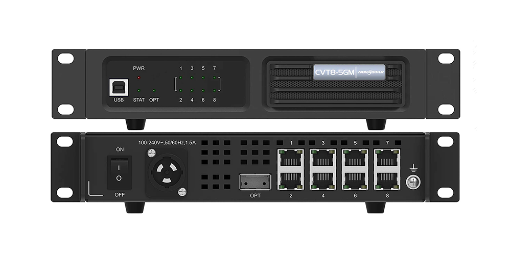
The NovaStar CVT8-5GM is a multimode LED display fiber converter with one 40 Gbit/s optical port and eight 5G BaseT Ethernet ports. It belongs to the NovaStar CVT8-5G family and uses an 850 nm optical module with an MPO connector. The documented optical reach is 100 m on OM3 or 150 m on OM4 fiber. Its main value is carrying multiple high-bandwidth LED data channels through one fiber trunk, then distributing them to compatible cabinets near the screen.
Choosing the right converter takes more than matching a connector. The controller output, optical modules, fiber assembly and receiving cards must form a supported system. This guide explains CVT8-5GM specifications, CVT8-5GM vs CVT8-5GS selection, wiring, commissioning and fault isolation. It also distinguishes hardware ratings from project-dependent decisions, so you can prepare a useful equipment list and avoid ordering a converter that does not match your LED wall.
1. What the NovaStar CVT8-5GM does
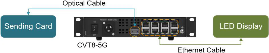
The NovaStar CVT8-5GM converts between optical and electrical signals in an LED control system. A typical documented 5G arrangement is: video source → compatible controller with 40G optical output → multimode fiber → CVT8-5GM → 5G receiving cards → LED modules. A controller equipped with the appropriate optical output can connect directly to the converter; a second converter is not automatically required at the control position.
01. Understand the CVT8-5G product family
CVT8-5G is the family name, while CVT8-5GM identifies the multimode version and CVT8-5GS identifies the single-mode version. Searches for “CVT8” or “NovaStar CVT8-5G” can therefore lead to specifications covering both models. Check the final letter on the quotation and optical module before selecting cable. Here, 5G means a 5-gigabit wired interface, not mobile-network connectivity.
02. Match the complete signal chain
NovaStar’s MX6000 Pro documentation separates a 1G solution using 4×10G output cards and CVT10-family converters from a 5G solution using a 1×40G output card, CVT8-5G and supported 5G receiving cards. Do not assume that an ordinary 1G receiving card becomes compatible because its RJ45 socket looks identical. Record the exact controller, installed output card, receiving-card model and firmware before approving a build.
The CVT8-5GM is a transmission device, not a video scaler, media player or general-purpose network switch. Screen mapping and source processing remain functions of the wider control system. Its 40 Gbit/s rating is not a universal pixel-capacity guarantee; usable loading depends on the supported controller configuration, frame rate, bit depth and receiving hardware.
2. CVT8-5GM at a glance
Use this CVT8-5GM summary for initial selection. The optical distance applies to the fiber segment, while the Ethernet runs from the converter to the cabinets require their own cable and length checks. Neither rating should be added to another without checking the complete system design.
| Item | Published specification | Practical check |
|---|---|---|
| Optical connection | 1 × 40 Gbit/s; 850 nm multimode | Confirm a matching controller-side optical module. |
| Ethernet outputs | 8 × 5G BaseT; up to 5 Gbit/s per port | Use a supported 5G receiving-card system. |
| Fiber and connector | OM3/OM4; 50/125 μm; 8-core multimode; MPO | Confirm assembly polarity and mating details. |
| Optical reach | 100 m on OM3; 150 m on OM4 | Measure the installed route, including patching. |
| USB control | Type-B; NovaLCT V5.4.0 or later for program upgrades | Separate converter servicing from screen mapping. |
| Power | 100–240 V AC; 50/60 Hz; 1.5 A input rating; 33 W rated consumption | Check distribution, grounding and connector access. |
Source: NovaStar COEX Wiki, “CVT8-5G,” front-panel, rear-panel and specifications sections, checked October 9, 2026. These are product ratings, not measurements taken on a particular installation. Keep the supplier’s matching specification revision with the project record.
Before requesting a price, give the supplier the route length, cabinet layout, receiving-card model, required frame rate and bit depth. Ask whether the quotation includes both optical modules, the correctly specified fiber and the rack hardware. A low converter-only price can conceal missing components that determine whether commissioning succeeds.
3. CVT8-5GM vs CVT8-5GS: which fiber type?
The CVT8-5GM vs CVT8-5GS decision starts with the installed fiber and required reach. Both belong to the same 5G converter family, but their optical interfaces require different cable systems. An adapter that physically joins connectors does not turn multimode optics into single-mode optics.
| Selection factor | CVT8-5GM | CVT8-5GS |
|---|---|---|
| Optical mode | Multimode | Single-mode |
| Wavelength | 850 nm | 1310 nm |
| Documented reach | 100 m OM3 / 150 m OM4 | 10 km |
| Fiber specification | OM3/OM4, 50/125 μm, 8-core | OS1/OS2, 9/125 μm, twin-core |
| Connector | MPO | LC |
| Suitable planning scenario | Compatible short venue trunk | Compatible longer site-wide route |
For example, a measured 120 m route exceeds the CVT8-5GM OM3 rating even if both devices are inside the same hall. OM4 may meet the published distance requirement, provided the modules and installed channel are suitable. A 180 m route exceeds both listed multimode ratings; investigate the CVT8-5GS single-mode converter and a matching system instead.
Include service loops, risers and patch leads when measuring. Straight-line distance between the control desk and screen is rarely the installed cable length. Existing LC single-mode infrastructure may favor the single-mode model even on a short route, whereas an existing qualified MPO multimode trunk may favor the CVT8-5GM.
Do not decide by “indoors versus outdoors” alone. Route length, fiber type, connector compatibility and environmental protection are separate questions. Retain the cable manufacturer’s bend-radius and pulling-tension limits in the installation plan, and obtain confirmation of the complete optical assembly before procurement.
4. Full CVT8-5GM specifications
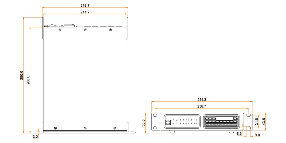
The CVT8-5GM specifications below cover the physical installation. They are useful for rack planning and operating conditions, but they do not establish an outdoor ingress-protection rating or certify a complete assembled rack.
| Parameter | Documented value |
|---|---|
| Rated consumption | 33 W; actual consumption varies with use and settings |
| Operating temperature | −20°C to +45°C in the current COEX Wiki |
| Operating humidity | 10%–80% RH, non-condensing |
| Storage conditions | −20°C to +70°C; 10%–95% RH, non-condensing |
| Dimensions | 254.3 × 50.6 × 290.0 mm |
| Net / gross weight | 2.26 kg / 3.26 kg |
| Listed certifications | RoHS, CE, FCC, IC, UL, CB; confirm applicability for the supplied unit |
01. Resolve specification revisions before installation
Earlier CVT8-5G documents circulate with different temperature and fiber entries. For planning, this guide uses the current COEX Wiki values and identifies the source rather than combining favorable numbers from different revisions. If an older CVT8-5GM is already in stock, ask for the documentation applicable to its hardware and optical module.
02. Evaluate the rack environment
Measure air temperature where the converter operates, not only at the room thermostat. A closed flight case beside other electronics may run substantially warmer than the venue. Keep ventilation paths clear and allow access to optical latches, cable strain relief and the power switch. Treat condensation after transport as an installation issue that must be resolved before energizing equipment.
The AC input current marking and rated wattage describe different aspects of the equipment. Plan power distribution using the complete rack specification and local installation requirements. Do not treat a wide input-voltage range as permission to use an unsuitable connector, ungrounded supply or improvised power cable.
5. Ports, panels and indicator lights
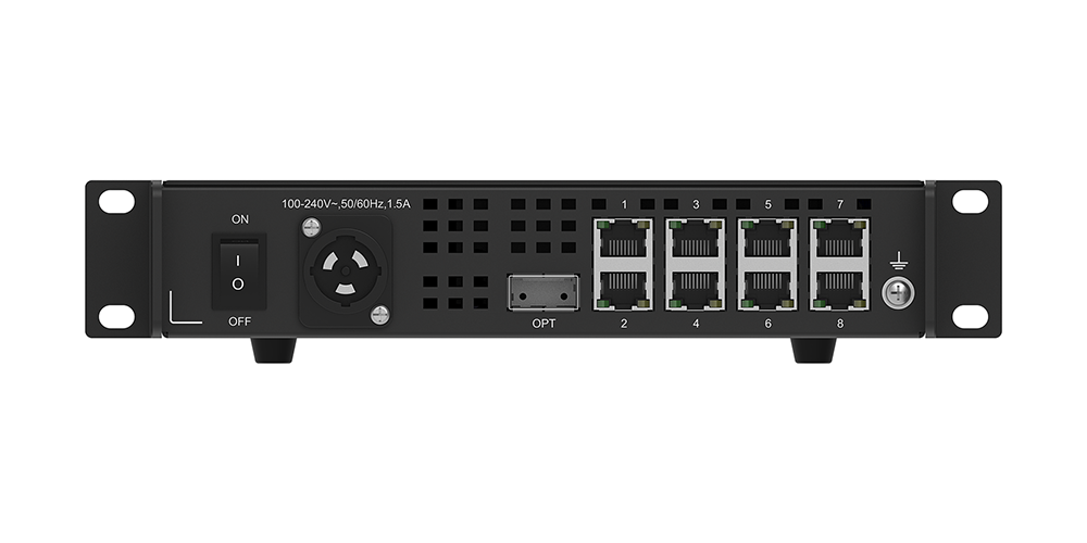
Learn the CVT8-5GM indicators before the unit is mounted out of easy reach. The front panel provides USB servicing and status indication; the rear carries the power input, OPT connection and numbered Ethernet ports. The USB connection should not be described as an extra rear-panel video input.
01. Read the indicators in sequence
PWR stays on when the power supply is normal. STAT flashes during normal operation. OPT1 stays on when the optical connection is normal. The front indicators numbered 1–8 show Ethernet cable connection status. At the rear Ethernet interfaces, solid green indicates a normal connection and flashing yellow indicates data activity.
These lights narrow the search area; they do not prove that the correct picture reaches every cabinet. A connected optical link can coexist with an incorrect source selection, unsupported receiving cards, excessive port loading or a mapping error. Check the relevant software status and the displayed test pattern as well.
02. Distinguish the two hot-plug rules
The CVT8-5GM optical module supports hot-swapping, but replacing it interrupts that signal path. Plan optical maintenance around the production schedule or a tested backup arrangement. NovaStar explicitly prohibits hot-plugging the PowerCON connector: isolate the supply before connecting or disconnecting that power connection.
The Type-B USB port is documented for upgrading the CVT8-5G program with NovaLCT V5.4.0 or later, and is not a cascading port. Do not route video through USB or connect it expecting to extend the optical channel. Label service cables separately from the display-data cables to prevent mistakes during a hurried changeover.
6. Where the CVT8-5GM is used
The NovaStar CVT8-5GM is useful when a compatible 5G LED wall needs a compact fiber trunk between the controller and the display area. Select it for a defined signal path, rather than assuming that every venue with a distant screen needs the same converter.
Rental stages: one optical trunk can simplify the run from front of house to the screen-side rack. Protect the MPO connection during repeated deployment, label both ends and carry a tested spare assembly. The route still has to remain within the selected OM3 or OM4 distance rating.
Fine-pitch indoor displays: high pixel density increases the importance of checking per-port loading and receiving-card capability. For indoor LED screen projects, establish the cabinet resolution and control architecture before ordering transmission hardware. Physical screen area alone does not determine bandwidth.
Studios and event production: the fiber segment avoids electromagnetic pickup along that optical path. It does not eliminate problems in power distribution, copper patch cables or source timing. Test the entire installation under its intended video settings, including any camera-facing production requirements.
Permanent venues: document patch-panel connections and reserve access for cleaning and replacement. If a building route is longer than 150 m, the CVT8-5GM is outside its published multimode reach even when the installation remains indoors. The right alternative follows the fiber route and supported control system.
7. How to connect the CVT8-5GM
Commission the CVT8-5GM on a short, known-good bench connection before installing the full route. This separates an equipment or compatibility problem from a cable-route problem. Keep the screen configuration backed up before changing an existing installation.
01. Confirm the design and connect the hardware
- Document the equipment. Record the controller, output-card model, optical-module labels, receiving cards and firmware. Verify the intended 40G optical-to-5G receiving-card arrangement with the applicable controller documentation.
- Mount and isolate power. Secure the converter and support the cables. With the supply isolated, connect the correct power cable. Leave the PowerCON connection undisturbed while energized.
- Prepare the optical channel. Check OM3 or OM4 identification, installed length, MPO mating details and polarity. Inspect and clean connector end faces using appropriate fiber tools before mating; never look into an active optical port.
- Connect the controller to OPT. Use matching supported optical modules at the two ends. Do not substitute an ordinary network transceiver solely because it fits the housing.
- Patch outputs to cabinets. Connect the CVT8-5GM numbered Ethernet outputs to the intended supported receiving-card chains. Follow the controller and cabinet documentation for cable category, maximum length and connection order.
02. Power up, map and verify
Energize the system and inspect PWR, STAT, OPT1 and the active Ethernet ports. In the controller’s supported screen-configuration software, confirm cabinet discovery, port assignments and receiving-card settings. For COEX workflows, follow the applicable VMP instructions; the converter’s NovaLCT USB upgrade procedure is a separate task.
Run a cabinet-identification pattern, then solid colors, grayscale and moving content at the intended frame rate and bit depth. Compare the physical cabinet order with the wiring drawing. A picture appearing on one cabinet is only an initial check, not acceptance of the whole wall.
For the CVT8-5GM handover record, retain the port map, configuration backup, module identifiers, cable lengths and test results. If a backup path is included, deliberately test its supported failover behavior before the system enters service.
8. Rack mounting and what is in the box
NovaStar describes the CVT8-5GM as half-1U in width and shows two units, or one unit with a connecting piece, assembled for a standard 19-inch rack. Use the manufacturer’s assembly drawing with the actual supplied brackets; the width description should not replace a check of mechanical dimensions and clearance.
The current COEX Wiki calls for a rack able to withstand at least four times the mounted equipment’s total weight and four M5 fixing screws. Installation is specified for a restricted-access location. A qualified installer should select fasteners and support appropriate to the rack and installation, including any transport or suspended-use requirements.
The documented CVT8-5G accessory list includes a power cord, USB cable, two 40G optical modules with one intended for the controller, two supporting brackets, a connecting piece, twelve M3×8 screws, an assembly diagram and a certificate of approval. Confirm the supplied package with the seller, especially for replacement, used or separately bundled equipment.
Fiber cable is a separate procurement check. Specify the complete assembly, length, connector orientation and polarity instead of ordering only “MPO cable.” Keep a packing checklist so that optical dust caps, rack parts and the controller-side module are not left behind during deployment.
For a touring CVT8-5GM rack, add clear port labels and strain relief without blocking ventilation. Provide enough service space to remove a module without pulling adjacent cables. Store cleaned spare fiber with protective caps and identify it as tested or untested.
9. CVT8-5GM vs CVT10
CVT8-5GM vs CVT10 is a system-architecture comparison, not simply eight ports versus ten. The CVT8-5GM belongs to the 40G optical / 5G Ethernet path, while the CVT10 family serves a different optical and Gigabit Ethernet arrangement. Port count alone cannot establish substitution.
Start with the receiving cards already installed in the cabinets. If they are part of a 1G system, check the controller’s supported 1G converter options rather than purchasing a CVT8-5GM as an assumed upgrade. A move to 5G may require changes elsewhere in the control chain and should be evaluated as a complete project.
Next, check the controller’s installed output hardware. A modular controller name by itself is insufficient because output-card selection changes the available transmission architecture. NovaStar’s published MX6000 Pro solution table explicitly distinguishes its 4×10G and 1×40G card paths.
Finally, compare the exact converter variant, module and required backup arrangement. Avoid borrowing a distance figure from another CVT model or optical module. Our NovaStar CVT10 specifications and setup guide provides a separate starting point for that family.
The CVT8-5GM has one optical port. It does not provide a second independent optical connection merely because transmission is bidirectional. Where continuity is essential, design redundancy using supported controllers, additional paths and the relevant backup configuration, then test the resulting behavior.
10. Troubleshooting the fiber link
For CVT8-5GM troubleshooting, work from power to optical transport, then Ethernet connections and screen configuration. Change one variable at a time. A short known-good fiber and a verified compatible cabinet are more useful than repeatedly changing unrelated settings.
| Observed symptom | First checks | Next isolation step |
|---|---|---|
| PWR off | Supply availability, switch and power-cable connection | Isolate power before inspecting or reseating PowerCON. |
| STAT not flashing normally | Startup behavior and power stability | Record the state and seek supplier support if persistent. |
| OPT1 off | Far-end power, matching optics, MPO seating and cleanliness | Test a qualified short fiber; check polarity and module seating. |
| One Ethernet link absent | Cable, receiving-card power and assigned port | Use a known-good patch lead and verify the supported card. |
| Links present but screen black | Source selection, blanking, mapping and compatibility | Use the controller test pattern to separate source from output issues. |
| Intermittent image or errors | Cable damage, connectors, temperature and output loading | Compare bench operation with the installed route at identical settings. |
A lit OPT1 indicator is evidence of an optical connection, not proof of an error-free picture at full operating load. Likewise, a dark Ethernet indicator does not prove the cable alone is defective; receiving-card power and hardware compatibility also matter.
NovaStar lists insertion loss and return loss under its optical-fiber selection specifications. Do not reinterpret an individual listed figure as a fully defined end-to-end channel budget without confirmation. Ask the optical supplier to qualify the assembled route, including connectors and patch panels, against the actual module requirements.
If the CVT8-5GM works on the bench but fails after installation, compare only the changed parts first. Record the affected ports, source format, firmware versions and whether the fault follows a cable or cabinet. This gives technical support reproducible evidence instead of a general “screen flickers” report.
11. FAQ: NovaStar CVT8-5GM
Select a question to expand the answer. These answers summarize the model-specific decisions most likely to affect purchasing and installation.
01. What is the difference between CVT8-5G and CVT8-5GM?
CVT8-5G is the product-family name. CVT8-5GM is its multimode version, while CVT8-5GS is the single-mode version. The suffix determines the optical module and fiber selection, so it should appear on the equipment schedule and purchase order.
02. How far can the NovaStar CVT8-5GM transmit?
The documented optical reach is 100 m with OM3 fiber or 150 m with OM4. Measure the complete installed optical route. For a longer path, assess a compatible single-mode solution rather than assuming that any fiber connection supports kilometers.
03. Which cable does the CVT8-5GM require?
NovaStar specifies OM3/OM4 multimode, 50/125 μm, 8-core fiber with an MPO connector. Confirm polarity and mating details for both modules and any intervening patching. An ordinary LC duplex lead is not a direct substitute.
04. Can the CVT8-5GM work with ordinary 1G receiving cards?
Do not assume compatibility. NovaStar documents CVT8-5G in its 5G solution alongside supported 5G receiving cards, while its 1G solution uses different converter options. Confirm the complete controller, output-card, converter and receiving-card combination before ordering.
05. Do I need two CVT8-5GM converters?
Not automatically. A compatible controller with the appropriate 40G optical output can feed a screen-side CVT8-5GM directly. The documented package includes a controller-side optical module. Other topologies require explicit confirmation in the relevant system documentation.
06. Where can I find the CVT8-5GM manual and firmware guidance?
Look for the family document titled CVT8-5G Fiber Converter Specifications and the CVT8-5G accessory page in NovaStar COEX Wiki. The converter program-upgrade connection uses USB Type-B and NovaLCT V5.4.0 or later. Obtain the correct firmware from the supplier for the actual hardware.
07. Does 40 Gbit/s mean a fixed maximum screen resolution?
No. CVT8-5GM link bandwidth is only one constraint. Controller capacity, frame rate, bit depth, receiving-card capability and per-port cabinet mapping determine usable loading. Use the applicable controller loading table instead of converting the headline bandwidth directly into a screen resolution.
08. What should a CVT8-5GM quotation include?
Request the exact model, optical modules, qualified fiber assembly, rack accessories, delivery terms and applicable warranty. Include the existing controller and receiving-card details. Pricing without a defined compatible package does not establish the total installed cost.
12. Conclusion, manual and specifications sources
The NovaStar CVT8-5GM is a practical choice when the project calls for a supported 40G optical-to-5G Ethernet connection over a qualified short multimode route. Confirm compatibility first, then match the optical modules and fiber, verify loading, and document the commissioning results. That sequence matters more than choosing by connector appearance or headline bandwidth.
For CVT8-5GM manual searches, use the family name CVT8-5G. The principal references for this guide are NovaStar’s COEX Wiki: CVT8-5G accessory page, its MX6000 Pro LED Display Controller Specifications V1.4.0 solution-build section, and the COEX loading-capacity guidance. Product documentation was checked on October 9, 2026. Practical planning and troubleshooting recommendations are guidance, not a claim that this article reports a laboratory test.
For converter servicing, see our NovaLCT software download and version archive, then confirm the version required by your equipment. Keep the controller’s own manual alongside the converter specification because mapping, loading and backup settings belong to the full system.
To plan an HonghaiLED display with a CVT8-5GM fiber link, contact our team with the screen resolution, cabinet arrangement, controller and receiving-card models, fiber type and measured route length. Those details allow the proposed equipment and cable package to be checked against your installation.
Related Posts
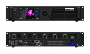
NovaStar CX40 Pro LED Controller: Specs, Setup and Manual
The NovaStar CX40 Pro is a 4K LED display controller…
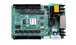
NovaStar MRV416-N Receiving Card: Specs, Setup & Manual
The NovaStar MRV416-N receiving card connects a compatible LED controller…
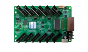
NovaStar MRV412-N Receiving Card: Specs, Firmware and Setup Guide
The NovaStar MRV412-N receiving card connects a compatible LED display…

No Comments