
NovaStar MRV416-N Receiving Card: Specs, Setup & Manual
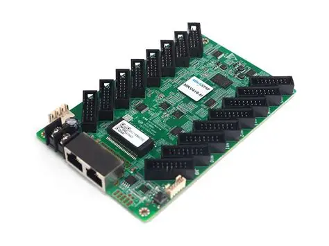
The NovaStar MRV416-N receiving card connects a compatible LED controller to the modules inside an LED cabinet. Its 16 HUB75E outputs support up to 32 parallel RGB data groups. For an 8-bit video source at 60 Hz, NovaStar specifies a maximum of 512 × 512 pixels with PWM driver ICs, or 512 × 384 pixels with common driver ICs. Those conditions belong with the capacity figure whenever you compare products.
Choosing the NovaStar MRV416-N involves more than counting pixels or matching an Ethernet connector. Installers need the module driver, scan arrangement, cabinet wiring, approved firmware, and a usable configuration backup. This guide explains those decisions, gives worked sizing examples, and separates local cabinet faults from problems elsewhere in the control chain.
Hardware references include NovaStar’s MRV416-N specification V1.0.3, dated May 20, 2025, and its NovaLCT documentation. Practical examples below are planning guidance, not approval for an untested cabinet. Keep the exact model suffix when requesting a manual, firmware package, price, or replacement.
1. What is the NovaStar MRV416-N Receiving Card?
The NovaStar MRV416-N is a receiving card, also called a receiver card. The video source feeds a processor or sending device, which sends LED display data to receivers. A receiver supplies the signals needed by its connected modules. It does not replace the video processor, media player, or LED power supply.
01. Understand the cabinet signal path
A typical path is source → compatible sending controller → LED data cable → receiving card → HUB75E ribbon cables → modules. The NovaStar MRV416-N belongs near the module end of that path. The screen layout assigns a defined image region to each receiver; cabinet wiring then determines where those pixels appear.
This distinction matters during service. If every cabinet loses video together, investigate the shared source and controller before replacing receivers. If one strip is wrong, inspect the corresponding module circuit, ribbon cable, and output assignment. A correctly detected card does not prove that its module parameters are correct.
02. Identify the board before ordering
Record the NovaStar MRV416-N label, module model, driver IC, current program version, and cabinet resolution. Searches for “MRV416N” or “MRV416 N” often describe this model, but MRV416 without the suffix is a different identifier. Similar names are insufficient evidence that firmware or replacement procedures are interchangeable.
Photograph the cable routing before disassembly. Include receiver labels and the direction of each module cascade. For an existing wall, preserve one verified working cabinet as the reference against which a repaired cabinet can be tested.
2. Key Features of the NovaStar MRV416-N Receiving Card
01. Evaluate display quality at operating brightness
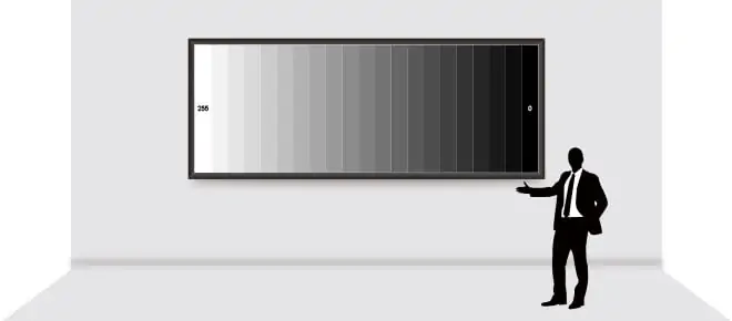
The NovaStar MRV416-N supports color management, 18bit+, pixel-level brightness and chroma calibration, seam adjustment, and independent RGB gamma adjustment. These are tools for commissioning a screen; they do not make every module combination perform identically. NovaStar’s MRV series overview describes calibration, readback, and backup functions.
Evaluate dark gradients, neutral gray, skin tones, and saturated colors at the brightness actually required on site. A full-white image is useful for checking uniformity but cannot reveal all low-grayscale problems. Match the content workflow to the display settings before adjusting individual cabinets.
Use calibration data appropriate to the installed modules. A color correction cannot repair a damaged LED, and electronic seam adjustment should follow checks for poor mechanical alignment. Keep a reference image and the previous settings so that a change can be compared objectively.
02. Use monitoring to shorten fault isolation
Mapping, temperature and voltage monitoring, communication diagnostics, and parameter readback make the NovaStar MRV416-N easier to maintain. Establish a commissioning baseline: normal readings, receiver order, and a photograph of the displayed mapping information. A later reading becomes more useful when you can compare it with that baseline.
For intermittent faults, record when the symptom occurs: cold startup, sustained bright content, cable movement, or a particular cabinet position. This evidence helps distinguish a power or connection problem from a software setting. Avoid changing several variables at once.
03. Define what backup actually protects
Signal-path backup and spare hardware serve different purposes. A redundant route may preserve data delivery during a supported cable fault, but it cannot replace a failed power supply or broken module. Test the configured backup path before relying on it at an event.
For NovaStar MRV416-N service, keep a separate project archive even when onboard backup is available. Factory-area parameters may not represent the latest commissioned settings. Label approved spares by cabinet type rather than placing every visually similar board in one undifferentiated box.
3. NovaStar MRV416-N Technical Specifications
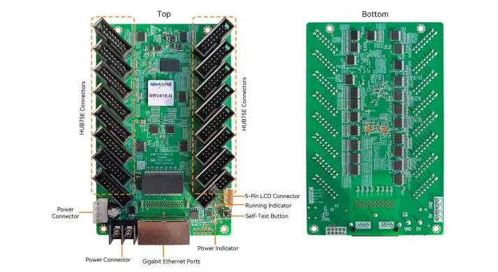
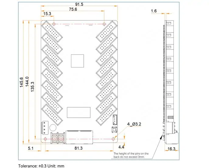
Use this NovaStar MRV416-N specification checklist for initial design review. The electrical figures describe the receiving card itself; they do not include LED module consumption. Detailed dimensions and connector drawings are in the manufacturer’s MRV416-N specification PDF, V1.0.3.
| Parameter | Published value | Design check |
|---|---|---|
| PWM driver capacity | 512 × 512 at 60 Hz, 8-bit source | Confirm the installed driver type |
| Common driver capacity | 512 × 384 at 60 Hz, 8-bit source | Use the applicable lower limit |
| Module outputs | 16 HUB75E; up to 32 parallel RGB groups | Match pinout and routing |
| Input supply | DC 3.8–5.5 V | Measure at the receiver under load |
| Rated card demand | 0.5 A; 2.5 W | Calculate module power separately |
| Operating conditions | −20 to +70°C; 10–90% RH, non-condensing | Check cabinet heat and moisture |
| Dimensions | 145.6 × 91.5 × 19.3 mm | Allow connector and cable clearance |
| Card mass | 104.6 g | Excludes cabinet and accessories |
Mechanical fit includes more than board length and width. Check standoffs, component clearance, access to connectors, and ribbon-cable bends. Request the structural drawing for manufacturing rather than scaling a photograph. Keep conductive debris away from the board during cabinet assembly.
The NovaStar MRV416-N specification is a hardware reference, not a complete cabinet design. Environmental protection, grounding, power distribution, and service access remain responsibilities of the finished display design. Confirm the supplied hardware revision before approving replacement stock.
4. Screen Capacity: Load Limits and Cabinet Math
01. Calculate the image region assigned to each receiver
For NovaStar MRV416-N load planning, calculate width and height in pixels first. Use the module’s documented pixel dimensions; rounded pixel-pitch labels can give misleading results. Multiply module columns by module pixel width, and module rows by module pixel height, then multiply the resulting cabinet dimensions.
| Example arrangement | Receiver image region | Pixel count | Initial assessment |
|---|---|---|---|
| 2 × 2 modules, each 128 × 128 | 256 × 256 | 65,536 | Below both published pixel totals |
| 4 × 3 modules, each 128 × 128 | 512 × 384 | 196,608 | At the common-driver stated limit |
| 4 × 4 modules, each 128 × 128 | 512 × 512 | 262,144 | At the PWM stated limit; beyond common-driver capacity |
Every row still needs driver, scan, timing, and data-group validation. A rectangle with the same total pixels but different dimensions is not automatically supported. Higher source bit depth or a different frame rate must be checked separately; do not extrapolate from an 8-bit, 60 Hz specification.
02. Separate HUB75E outputs from sender-port capacity
The NovaStar MRV416-N has 16 module connectors, but that does not establish a capacity of 16 cabinets. A connector is an electrical interface, not a universal cabinet unit. Modules can have different data requirements and supported cascade arrangements. The cabinet designer determines how outputs are assigned.
For example, dividing 262,144 by a 128 × 128 cabinet’s 16,384 pixels gives 16 mathematically. It does not prove that one receiver can wire, scan, and service 16 separate cabinets. Many installations use a receiver within each cabinet. Count the required receivers from the actual cabinet architecture.
Next calculate the sum of cabinet pixels assigned to each sending-controller output, using that controller’s limits. Do not treat the receiver’s Ethernet sockets as independent pixel budgets. A wall can satisfy every local receiver limit yet overload a sender output or have incorrect screen mapping.
5. MRV416-N vs MRV412-N vs MRV208-N
Compare the NovaStar MRV416-N with alternatives by cabinet routing and supported functions. The extra outputs are useful when the module arrangement needs them; they do not automatically increase the maximum resolution or improve color quality.
| Check | MRV416-N | MRV412-N | MRV208-N |
|---|---|---|---|
| HUB75E outputs | 16 | 12 | 8 |
| Parallel RGB groups | 32 | 24 | 16 |
| Selection priority | More parallel output connections | Cabinets requiring fewer connections | Lower connector-count layouts |
| Before substitution | Check physical fit, driver support, firmware, pinout, configuration, and controller compatibility | ||
References: NovaStar’s MRV series comparison and MRV208-N specification V1.0.2. The latter explicitly attaches its loading figures to M3 controllers and removes dual configuration-parameter backup from its listed features. Do not describe all three cards as functionally identical.
For the 12-output option, our MRV412-N receiving card guide covers that model separately. A replacement proposal should explain which wiring changes, files, and commissioning steps are required. Test an alternative receiver with the actual modules before buying a batch.
6. Installation and Setup in NovaLCT
01. Prepare files and wire one cabinet
Begin NovaStar MRV416-N setup with a verified cabinet file and a written connection plan. Isolate power before changing power leads or ribbon cables. Check polarity, mounting clearance, connector orientation, and module power distribution. Connect the controller’s designated LED output, not an unrelated network-control socket.
Label the incoming and outgoing data cables. Use one cabinet for initial commissioning so an incorrect parameter set cannot disrupt the whole wall. Record the current configuration before making changes to an existing installation.
02. Load and verify the receiving-card parameters
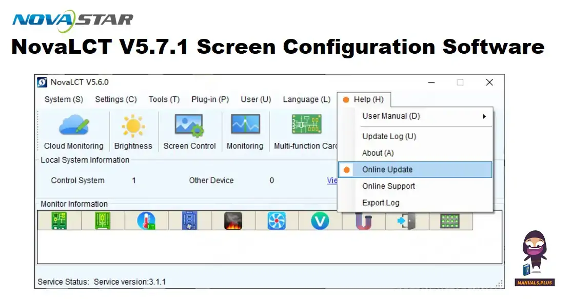
Use the NovaLCT release approved for the installed controller and receiver program. The NovaLCT download and manual archive helps locate software documentation. In the supported workflow, select the connected system, open Screen Configuration, and load the matching receiving-card configuration on the Receiving Card tab.
Confirm the target receiver before sending parameters. Check module dimensions, scanning, cabinet dimensions, and data order against the supplied design. Use the applicable Save function to retain verified settings in hardware; exporting a file to the computer serves a different purpose. NovaStar’s NovaLCT synchronous-control manual documents these concepts; labels can differ between releases.
A NovaStar MRV416-N configuration file is specific to the cabinet electronics. If no verified file exists, request the module datasheet and supplier assistance. Smart Settings should be based on known hardware information, not repeated guesses at driver type or scan timing.
03. Map the wall and confirm restart behavior
Configure screen connections to match the physical receiver sequence and cabinet coordinates. Display numbered blocks or a grid to expose duplicate regions, reversed chains, and displaced cabinets. Then check primary colors, white, gray ramps, dark content, and moving images at the intended brightness.
After saving, perform a controlled restart and verify that the NovaStar MRV416-N setup returns correctly. Archive the cabinet file, screen mapping, firmware identification, and calibration information required by the project. A spare is ready only after its restore procedure has been tested.
For handover, give the operator a simple acceptance record: cabinet inventory, controller output assignments, normal brightness, tested input format, and locations of the recovery files. Record which cabinet was used to validate the spare. Include a photograph of the final cable route so that a future technician can distinguish an intentional layout from an accidental reconnection.
Run the final test with representative content for the application, not only static test colors. Watch for faults after the cabinet warms up, and confirm that connectors remain mechanically secure. If the display will be filmed, keep the camera settings used for acceptance alongside the screen settings. That makes later comparisons meaningful when a new camera or content source is introduced.
7. Troubleshooting: Indicator Codes and Common Faults
For NovaStar MRV416-N troubleshooting, identify the affected area before changing settings: one module, one cabinet, a downstream chain, or the whole wall. Record the running indicator and the last known working state. The following table pairs common symptoms with practical checks.
| Observation | Next check | Avoid assuming |
|---|---|---|
| Whole wall blank | Source selection, controller output, shared signal path | Every receiver failed simultaneously |
| One cabinet blank | Local supply, incoming cable, cabinet parameters | New firmware is the first remedy |
| One strip or module incorrect | Ribbon seating, module power, output routing | Total pixel capacity explains every fault |
| Correct local pattern, wrong video | Source, screen mapping, controller settings | The complete signal chain is proven |
| Failure with bright content | Voltage drop, thermal conditions, power connectors | The receiver rating covers module demand |
01. Interpret indicators before resetting
NovaStar’s MRV416-N specification lists these green-indicator patterns: once per second for normal operation; once every three seconds for an abnormal Ethernet connection; three flashes per half-second when video input is unavailable; once every 0.2 seconds when running the backup program; and eight flashes per half-second after loop-backup switchover. The red power indicator normally stays lit.
These indications narrow the investigation; they do not replace cable and power checks. Record a short video if a rapid pattern is difficult to count. Compare the behavior with the manual for the actual board before attempting program recovery.
02. Isolate the module side carefully
The NovaStar MRV416-N local test is accessed by disconnecting Ethernet and pressing the self-test button twice; subsequent presses change the pattern. A good pattern suggests that part of the receiver-to-module path works. It does not establish correct video mapping, every timing setting, or reliable operation under sustained load.
Swap one known-good cable or compatible component at a time and repeat the same test. For a backup-program condition, preserve available readback information and consult the supplier about the approved recovery package. Restoring factory parameters blindly may replace settings needed by the installed cabinet.
8. Typical Applications for LED Display Projects
The NovaStar MRV416-N can be considered for rental, fixed-installation, and creative screens when its interfaces and performance match the cabinet. Select it around the module electronics and service plan, rather than assuming that a large screen always needs the card with the most outputs.
01. Match acceptance testing to the application
For rental work, prioritize labeled cables, a verified spare, and a repeatable mapping check after each assembly. For fixed signage, document access routes and compare temperature and power behavior during sustained operation. An outdoor cabinet must provide the environmental protection required at the site; the bare receiver is not a weatherproof enclosure.
For conference rooms or camera-facing stages, test low-brightness gradients and actual camera settings. Source frame rate and LED refresh rate describe different processes. The 60 Hz loading condition does not specify the final module refresh rate or guarantee a band-free recording.
02. Request a usable price and replacement package
A NovaStar MRV416-N price request should state quantity, board identification, module driver, cabinet resolution, destination, and required support. Ask whether the quote includes configuration verification, testing, delivery, and service spares. No single online listing establishes the landed cost of your project.
For an older installation, confirm current availability and the approved replacement path before ordering. A proposed successor requires its own compatibility check. Request a tested sample when changing hardware generations, and compare the total commissioning effort as well as the board price.

9. Compatibility With NovaStar Control Systems
01. Confirm the complete controller combination
NovaStar MRV416-N compatibility depends on the sending device, receiver program, module driver, and software workflow. The NovaStar brand and an RJ45-shaped socket alone do not establish interoperability. Ask for confirmation of the exact controller model and firmware combination, especially when moving between control-system generations.
Feature compatibility is a separate check from basic image output. Low-latency operation requires the supported driver condition; NovaStar describes a one-frame delay at the receiver end with driver ICs that include RAM. Other stages still contribute delay. For live camera work, measure the full path rather than quoting that receiver figure as total system latency.
02. Separate the manual, firmware, and cabinet files
When searching for a NovaStar MRV416-N manual PDF, use the hardware specification for electrical limits, connectors, and dimensions. Use the NovaLCT manual for software operations. The specification’s V1.0.3 document number is not a firmware version to install.
For a NovaStar MRV416-N firmware download, request an approved package for the exact board and module driver. Record the installed version and the reason for changing it. Obtain releases through the manufacturer or the responsible supplier, preserve the working configuration, and test on an isolated cabinet before extending an update across the wall.
RCFG and RCFGX files describe receiving-card parameters; a screen-connection file describes arrangement and mapping. Calibration data may require its own backup. Keep these resources with a cabinet photograph and a short restore procedure. A folder full of unexplained file names is a poor recovery plan during an urgent repair.
A useful service record has separate entries for the receiver model, program version, NovaLCT version, cabinet-file name, and screen-connection revision. Add a date and a short explanation whenever one changes. Before a maintenance visit, verify that the archive can be opened and that the technician has the correct connection method. This preparation reduces the temptation to download an unverified file while the display is already offline.
10. FAQs
These answers cover frequent NovaStar MRV416-N selection and maintenance questions. Expand a question to read the answer.
01.How many pixels can the NovaStar MRV416-N drive?
For 8-bit video at 60 Hz, the stated maximum is 512 × 512 with PWM drivers or 512 × 384 with common drivers. Confirm driver support, scan arrangement, output routing, and dimensional restrictions before treating a cabinet as compatible.
02. Where can I find the NovaStar MRV416-N manual PDF?
Use the linked NovaStar hardware specification in Section 3 for board information. For configuration operations, use the NovaLCT manual matching your workflow. Check the full model suffix and keep document revisions separate from software and firmware versions.
03. Is there a universal NovaStar MRV416-N RCFGX file?
No. Cabinet parameters must match the installed module driver, scan mode, pixel dimensions, and data routing. Obtain a supplier-approved file or a verified backup from a matching cabinet. Keep screen mapping and calibration information as required by the installation.
04. Can MRV416 firmware be used on MRV416-N?
05. Do 16 HUB75E connectors mean 16 cabinets per card?
06. Why is my NovaStar MRV416-N cabinet black?
07. Does the NovaStar MRV416-N support 3D and low latency?
08. What should a NovaStar MRV416-N quotation include?
11. Conclusion
The NovaStar MRV416-N receiving card is useful when a cabinet needs its 16 HUB75E outputs and 32 parallel RGB groups. Reliable selection starts with the module driver, pixel dimensions, scanning, and approved control-system combination. The maximum resolution is a conditional limit, not a shortcut around cabinet engineering.
For a dependable NovaStar MRV416-N installation, validate one cabinet, map the complete wall, save settings to hardware, and verify a restart. Keep a tested recovery archive and an identified spare. To request a configuration review or replacement quotation, contact HonghaiLED with the receiver label, module details, controller model, and wiring plan.
Related Posts
NovaStar CX40 Pro LED Controller: Specs, Setup and Manual
The NovaStar CX40 Pro is a 4K LED display controller…
NovaStar CVT8-5GM Fiber Converter: Specifications, Setup and Manual
The NovaStar CVT8-5GM is a multimode LED display fiber converter…
NovaStar MRV412-N Receiving Card: Specs, Firmware and Setup Guide
The NovaStar MRV412-N receiving card connects a compatible LED display…

No Comments