
NovaStar CVT8-5GS Fiber Converter: Specs, Setup and Manual
The NovaStar CVT8-5GS is a single-mode fiber converter for LED displays. It converts the electrical video signal coming from a sending card into optical signals, carries them down a single-mode fiber link, and converts them back to Ethernet at the far end of the run. That removes the 100 m limit of copper cable: the CVT8-5GS optical port is rated for up to 40 Gbit/s and up to 10 km, and its eight 5G BaseT ports feed the receiving cards that drive the screen.
This guide covers the CVT8-5GS specifications, port layout, indicator lights, single-mode vs multi-mode selection, step-by-step connection, rack mounting, troubleshooting and the questions installers ask most often.
Last updated: September 21, 2026
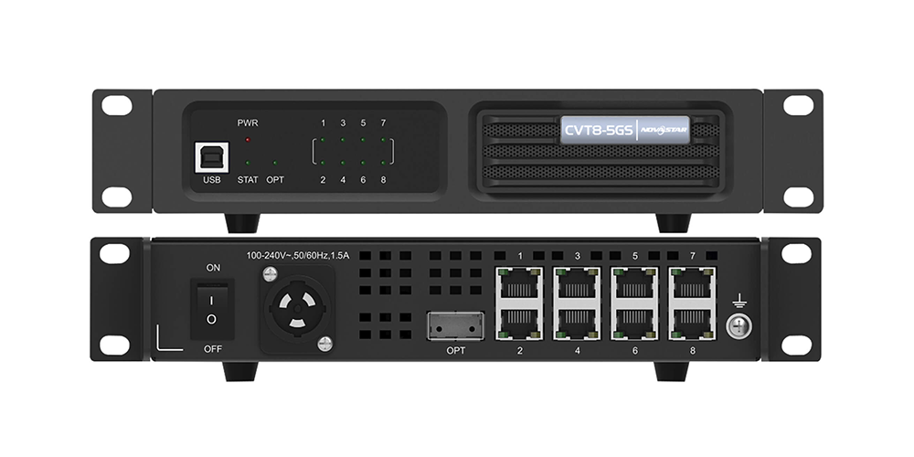
Table of Contents
1. What the NovaStar CVT8-5GS does
2. CVT8-5GS at a glance
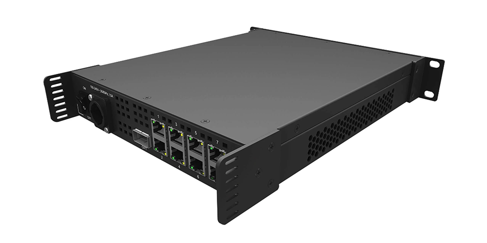
3. Ports, panels and indicator lights
4. Full CVT8-5GS specifications
5. CVT8-5GS or CVT8-5GM: choosing the fiber type
6. How to connect the CVT8-5GS (step by step)
7. Rack mounting and what is in the box
8. CVT8-5GS vs CVT10
9. Where the CVT8-5GS is used
10. Troubleshooting the fiber link
11. FAQ: NovaStar CVT8-5GS
12. Sources, download and related reading
1. What the NovaStar CVT8-5GS does
A fiber converter exists for one reason: copper Ethernet cable loses signal after roughly 100 m, and LED stages, stadium screens and city billboards are usually much further than that from the control room. The CVT8-5GS solves the problem by turning the signal into light.
In a typical installation, the signal path looks like this:
Video source → LED controller / sending card → CVT8-5GS → single-mode fiber → converter at the display → receiving cards → LED screen
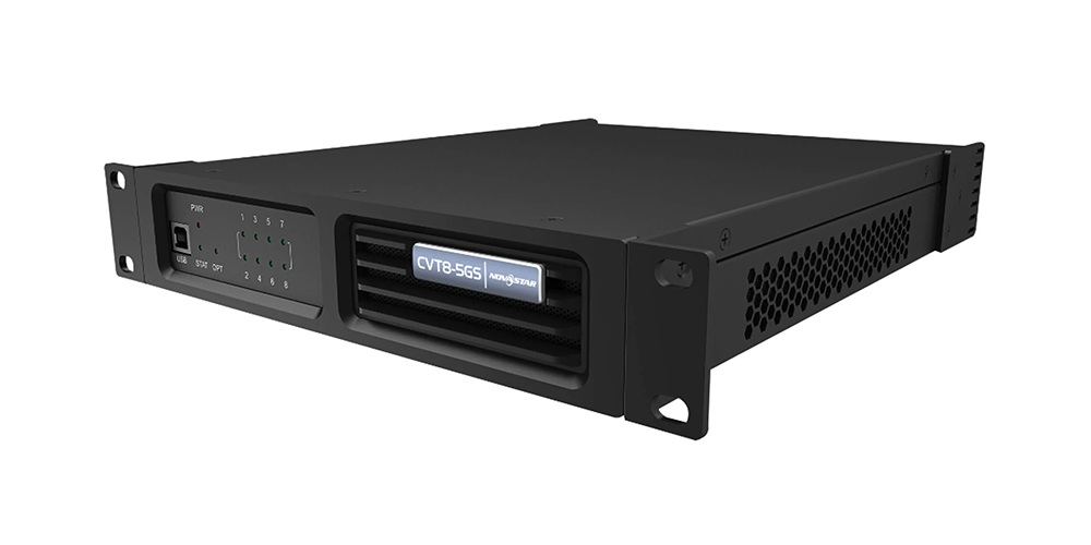
The CVT8-5GS is a bi-directional converter: it handles the conversion between optical signals and electrical signals in both directions, and NovaStar supplies two 40G optical modules with each unit (one for the controller) so both ends of the link are covered. Because the data travels as light rather than as an electrical current, the link is immune to electromagnetic interference from dimmers, motors, generators and power cables.
The CVT8-5GS is the single-mode member of the CVT8-5G family. The hardware, the eight Ethernet ports and the 40 Gbit/s optical port are shared with the multi-mode CVT8-5GM; the difference is the optical module, the connector and the reach.
2. CVT8-5GS at a glance
| Product type | Fiber converter for LED display signal transmission (CVT8-5G family) |
| Model | CVT8-5GS — single-mode |
| Optical port | 1 × 40 Gbit/s, hot-swappable module, 1310 nm |
| Ethernet ports | 8 × 5G BaseT, up to 5 Gbit/s each |
| Transmission distance | Up to 10 km (rated module distance) |
| Fiber type | OS1/OS2 single-mode twin-core, 9/125 µm, LC connector |
| Control port | 1 × USB Type-B (firmware upgrade with NovaLCT V5.4.0 or later) |
| Power | 100–240V~, 50/60Hz, 1.5A PowerCON; 33 W rated consumption |
| Mounting | Half-1U; horizontal, suspended or 19-inch rack |
| Certifications | CCC, RoHS, CE, FCC, IC, UL, CB |
3. Ports, panels and indicator lights
The front panel carries the diagnostic LEDs and the USB control port; the rear panel carries power, the optical port and the eight Ethernet ports. Reading the indicators correctly is the fastest way to diagnose a fiber link, so it is worth knowing them before you climb a truss.
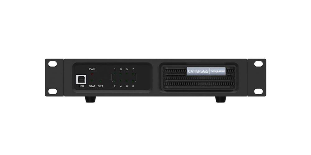
Front panel
| Item | Purpose |
| USB Type-B | Connects to a control computer (NovaLCT V5.4.0 or later) to upgrade the converter firmware. It is not a cascading port. |
| PWR | Power indicator. Always on when the power supply is normal. |
| STAT | Running indicator. Flashing means the device is functioning normally. |
| OPT1 | Optical port indicator. Always on when the fiber connection is normal. |
| 1–8 | Ethernet port indicators. Always on when the Ethernet cable connection is normal; flashing yellow during data transmission. |
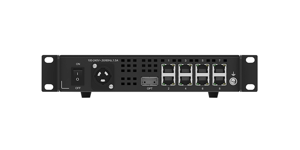
Rear panel
| Connector | Type | Notes |
| OPT | 40G optical port | Hot-swappable optical module. CVT8-5GS uses a 1310 nm single-mode module; the CVT8-5GM uses an 850 nm multi-mode module. |
| 1–8 | 8 × 5G BaseT Ethernet | Solid green means the cable connection is normal; flashing yellow means data is transmitting. |
| USB | USB Type-B | Control port for configuration and firmware upgrades. |
| Power | PowerCON | 100–240V~, 50/60Hz, 1.5A. The PowerCON connector must not be plugged in hot. |
4. Full CVT8-5GS specifications
| Electrical specifications | |
| Power supply | 100–240V~, 50/60Hz, 1.5A |
| Rated power consumption | 33 W |
| Operating environment | |
| Temperature | –20°C to +55°C |
| Humidity | 10% RH to 80% RH, non-condensing |
| Storage environment | |
| Temperature | –20°C to +70°C |
| Humidity | 10% RH to 95% RH, non-condensing |
| Physical specifications | |
| Dimensions | 254.3 mm × 50.6 mm × 290.0 mm (tolerance ±0.3 mm) |
| Net weight | 2.26 kg (product only) |
| Gross weight | 3.26 kg (product, accessories and packing) |
| Optical module (CVT8-5GS) | |
| Transmission rate | 40 Gbit/s |
| Wavelength | 1310 nm |
| Transmission distance | 10 km |
| Fiber model / mode | OS1/OS2, single-mode twin-core, 9/125 µm |
| Connector type | LC |
| Insertion loss / return loss | ≤ 0.3 dB / ≥ 45 dB |
| Packing information | |
| Outer box | 387.0 mm × 173.0 mm × 359.0 mm, kraft paper box |
| Packing box | 362.0 mm × 141.0 mm × 331.0 mm, kraft paper box |
Note: the operating temperature range in this table follows NovaStar’s published CVT8-5G specification (V1.0.0), which rates the unit from –20°C to +55°C.
5. CVT8-5GS or CVT8-5GM: choosing the fiber type
Both models share the same chassis, the same eight Ethernet ports and the same 40 Gbit/s optical bandwidth. They differ in the optical module and therefore in the cable you must pull through the venue:
| Specification | CVT8-5GS (single-mode) | CVT8-5GM (multi-mode) |
| Wavelength | 1310 nm | 850 nm |
| Transmission distance | 10 km | 100 m |
| Fiber model | OS1/OS2 | OM3 |
| Fiber mode | Single-mode twin-core, 9/125 µm | Multi-mode 8-core, 50/125 µm |
| Connector | LC | MPO |
| Insertion loss / return loss | ≤ 0.3 dB / ≥ 45 dB | ≤ 0.1 dB / ≥ 50 dB |
| Best for | Long runs between buildings, stadiums, billboards, control rooms | Short runs inside one venue or one stage |
Rule of thumb: if the run is longer than 100 m, or leaves the building, choose the CVT8-5GS and OS1/OS2 single-mode cable. If everything stays inside one venue, the CVT8-5GM multi-mode converter is usually the simpler choice because MPO trunk cables are quicker to deploy on site.
6. How to connect the CVT8-5GS (step by step)
- Mount the unit first. Fix the CVT8-5GS on a flat surface, suspend it, or mount it in a 19-inch rack using the brackets and screws supplied. Leave the front and rear panels accessible so you can read the LEDs.
- Power the converter. Connect the PowerCON cable to a 100–240V~ supply. Never hot-plug the PowerCON connector — switch the supply off before connecting or disconnecting it.
- Check the optical module. The 40G module sits in the OPT port on the rear panel. It is hot-swappable, but for a new installation fit the single-mode module before you connect the fiber, and keep the dust caps on until the last moment.
- Run and connect the single-mode fiber. Use OS1/OS2 9/125 µm twin-core cable with LC connectors. Keep insertion loss at or below 0.3 dB and return loss at or above 45 dB, and clean every LC ferrule before mating. Avoid tight bends in the cable.
- Connect the Ethernet ports. Patch the eight 5G BaseT ports to the sending card and the receiving cards. Each port supports up to 5 Gbit/s, and the LED beside it lights solid green when the cable connection is good.
- Power up and read the indicators. PWR should be solid on, STAT should be flashing, and OPT1 should be solid on once the fiber link is up. If OPT1 stays dark, the fiber link is the problem, not the display configuration.
- Update firmware if needed. Connect a computer to the front USB Type-B port and use NovaLCT V5.4.0 or later to upgrade the converter program. Do this before the show, not during it.
If you are also wiring the cards at either end of the chain, our guides to the MSD600 sending card and the MRV412-N receiving card explain how the signal is generated and how it is handed back to the cabinets.
7. Rack mounting and what is in the box
A single CVT8-5GS is half-1U wide. Two converters, or one converter plus the supplied connecting piece, combine into a 1U assembly that fits a standard 19-inch rack. NovaStar specifies four M5 screws for the assembly (at least M5×12 where the rack calls for it) and a rack that can carry at least 9 kg — roughly four times the weight of the mounted equipment. If the rack is enclosed, check the ambient temperature inside the rack, not just the room, and make sure airflow around the unit is not blocked.
Each CVT8-5GS ships with:
- 1 × power cord and 1 × USB cable
- 2 × 40G optical modules (one for the controller)
- Supporting bracket A (with nuts) and bracket B (without nuts)
- 1 × connecting piece and 12 × M3×8 screws
- 1 × assembling diagram and 1 × certificate of approval
8. CVT8-5GS vs CVT10
| Specification | CVT8-5GS | CVT10 |
| Optical ports | 1 × 40 Gbit/s | 2 × 10G |
| Ethernet ports | 8 × 5G BaseT (up to 5 Gbit/s each) | 10 × Gigabit Ethernet (up to 1 Gbit/s each) |
| Fiber variants | CVT8-5GS (single-mode) / CVT8-5GM (multi-mode) | CVT10-S (single-mode) / CVT10-M (multi-mode) |
| Typical reach | Up to 10 km single-mode / 100 m multi-mode | Up to 2 km single-mode / 500 m multi-mode |
| Choose it when | You need the highest port bandwidth per converter and very long single-mode runs | You need more Ethernet ports per unit and the run stays inside a few kilometres |
Both converters solve the same problem — getting LED display data across a distance that copper cannot cover — but they trade port count against bandwidth and reach. Read the full NovaStar CVT10 fiber converter guide if your project needs more Ethernet ports or a 2 km single-mode link.
9. Where the CVT8-5GS is used
- Rental and staging: a single-mode fiber run replaces several hundred metres of copper between the FOH position and the stage, and the half-1U chassis travels easily in a rack drawer.
- Large outdoor events and billboards: the optical link reaches across a site, a highway or a stadium bowl without repeaters, and is unaffected by the electrical noise around generators and lighting rigs.
- Permanent installations: malls, transport hubs and building facades where the control room sits far from the screen and cable routes are long or congested.
- Broadcast and live production: studios and OB setups that need a stable, low-latency link between the video source and the display wall.
- Corporate events and trade shows: venues where the control desk is on the other side of a hall and the cable route crosses public areas.
If you are planning a full screen instead of a single link, our LED display project examples show how controllers, converters and cabinets come together on real installations.
10. Troubleshooting the fiber link
Work through the indicators in order. They tell you whether the fault is power, the fiber, the copper patch or the display configuration.
| Symptom | What it means | What to check |
| PWR is off | No power to the converter | PowerCON connection, supply voltage, and whether the PowerCON was plugged in hot |
| STAT is not flashing | The unit is not running normally | Remove and reseat power; if it still does not flash, contact your supplier |
| OPT1 is off | The optical link is down | Fiber polarity and seating, dirty LC ferrules, a damaged or over-bent cable, and whether the far-end module is powered |
| An Ethernet LED (1–8) is off | That copper patch is not connected | The RJ45 at both ends, the port assignment on the sending/receiving card, and the cable itself |
| Ports are up but the screen is black | The link is healthy; the problem is downstream | Screen configuration in NovaLCT, receiving card mapping, and whether each Ethernet port is mapped to the correct cabinet range |
| Image drops under load | Bandwidth, mapping or cable quality | Port loading against the 5 Gbit/s per-port rating, and fiber insertion loss against the 0.3 dB limit |
11. FAQ: NovaStar CVT8-5GS
╸What is the NovaStar CVT8-5GS used for?
The CVT8-5GS converts between optical and electrical signals so an LED display can be driven over distances that copper Ethernet cannot cover. It sits between the sending card and the receiving cards and carries the display data over single-mode fiber.
╸How far can the CVT8-5GS transmit a signal?
The CVT8-5GS optical module is rated for 1310 nm transmission over OS1/OS2 single-mode fiber at distances up to 10 km. The multi-mode CVT8-5GM is rated for 100 m over OM3 fiber.
╸What is the difference between the CVT8-5GS and the CVT8-5GM?
Only the optical module and the cable type differ. The CVT8-5GS is single-mode: 1310 nm, LC connectors, OS1/OS2 cable, 10 km. The CVT8-5GM is multi-mode: 850 nm, MPO connectors, OM3 cable, 100 m. Both have one 40 Gbit/s optical port and eight 5G BaseT Ethernet ports.
╸How many Ethernet ports does the CVT8-5GS have, and how fast are they?
The CVT8-5GS has eight 5G BaseT Ethernet ports, each rated up to 5 Gbit/s, plus one optical port rated up to 40 Gbit/s.
╸Can I replace the optical module without switching the converter off?
Yes. The 40G optical module is hot-swappable, so it can be replaced without powering the converter down. Power down for safety if you are working in a rack with restricted access.
╸Which fiber cable does the CVT8-5GS need?
Use OS1/OS2 single-mode twin-core fiber, 9/125 µm, with LC connectors. NovaStar specifies insertion loss of 0.3 dB or less and return loss of 45 dB or more for the CVT8-5GS link.
╸Can the CVT8-5GS be mounted in a standard 19-inch rack?
Yes. One unit is half-1U wide, so two units — or one unit plus the supplied connecting piece — form a 1U assembly for a standard 19-inch rack. Fix it with four M5 screws and make sure the rack can carry at least 9 kg.
╸What software do I need to update the CVT8-5GS firmware?
NovaLCT V5.4.0 or later, connected to the front USB Type-B port with a standard USB cable. The USB port is for configuration and firmware upgrades only — it is not used to cascade converters.
12. Sources, download and related reading
Source: NovaStar CVT8-5G Fiber Converter Specifications, document version V1.0.0 (released 2022-07-10), Xi’an NovaStar Tech Co., Ltd. Specifications in this guide follow that document; the CVT10 figures come from our CVT10 product guide.
Download: NovaStar CVT8-5G Fiber Converter Specifications (PDF, document version V1.0.0) — the full official specification sheet for the CVT8-5GS, including the optical module, fiber, power and environmental data used in this guide.
Related reading on this site:
- NovaStar CVT8-5GM multi-mode fiber converter explained
- NovaStar CVT10 fiber optic converter for long-distance LED control
- NovaLCT download: software, manuals and archive
- NovaStar MSD600 LED sending card guide
- NovaStar MRV412-N receiving card: specs and setup
- More LED control system guides
Related Posts
NovaStar MX6000 Pro Video Wall Controller: Specs, Price & Manual
NovaStar MX6000 Pro in one paragraph: the NovaStar MX6000 Pro…
NovaStar H5 Video Wall Splicer: Specs, Setup & Manual
The NovaStar H5 video wall splicer is a 5U, modular…
NovaStar TB10 Plus: Specifications, Setup and TB20 Plus Comparison
The NovaStar TB10 Plus is an Android 10 multimedia player…

No Comments