
NovaStar CVT10 Fiber Converter: Specs, Setup & Manual
The NovaStar CVT10 fiber optic converter connects a compatible LED sending system to a distant LED display by converting between electrical and optical signals. The CVT10-S uses single-mode fiber for links rated up to 10 km, while the CVT10-M uses multimode fiber for links rated up to 300 m. Both provide two optical ports and ten physical Gigabit Ethernet ports, but the number of usable outputs depends on the upstream optical format.
Choosing a NovaStar CVT10 involves more than comparing transmission distances. The controller, optical modules, installed fiber, port allocation, and backup design must work together. This guide explains the specifications, CVT10-S versus CVT10-M selection, installation, manual and firmware requirements, troubleshooting, and the information needed for an accurate quotation. It also identifies differences between NovaStar’s published specification sources so you can check the exact supplied unit before ordering.
1. NovaStar CVT10 specifications and revision checks
The NovaStar CVT10 is a transport device in the LED signal chain. Its physical interfaces do not establish the total screen capacity by themselves. Start with the controller’s output mapping, then confirm the converter and optical link required for each group of receiving cards.
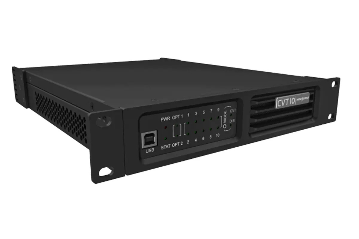
| Item | Published information | What to check |
|---|---|---|
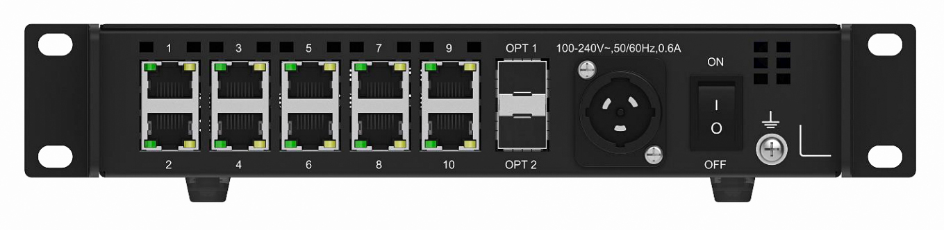
| Interfaces | Two optical ports; ten Gigabit Ethernet ports; USB Type-B control | Active output group and controller compatibility |
| Optical roles | OPT1 primary; OPT2 backup in CVT mode | Do not count the backup as another ten independent outputs |
| Power consumption | V1.3.7 PDF: 18 W; product webpage: 22 W | Use the supplied unit’s label and matching documentation |
| AC input | Both list 100–240 V, 50/60 Hz; PDF: 0.6 A; webpage: 0.7 A | Confirm the power connector and nameplate |
| Operating temperature | PDF: −20 to +55°C; webpage: −20 to +60°C | Confirm the applicable limit before enclosure design |
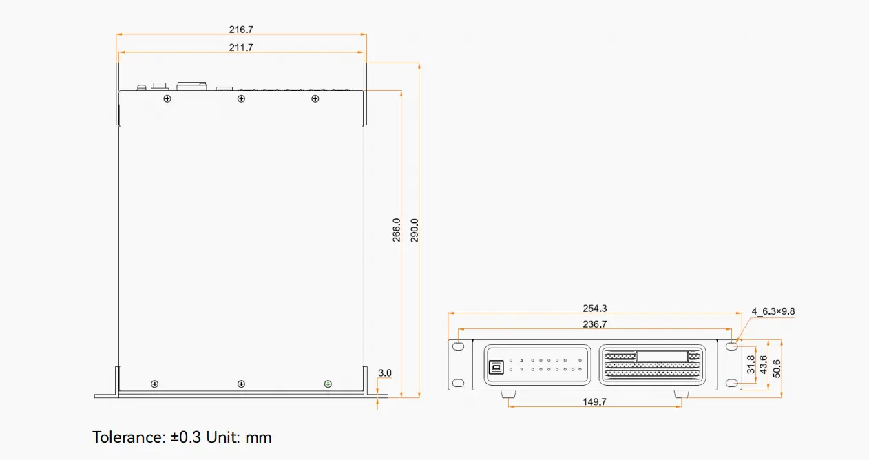
| Dimensions | PDF: 254.3 × 50.6 × 290.0 mm; webpage: 254.3 × 50.1 × 290.0 mm | Check the mechanical drawing for the delivered revision |
| Weight | Net: 2.1 kg in both; packed: 3.7 kg in PDF, 3.1 kg on webpage | Obtain shipment weight for freight planning |
Source note: These differences were checked against NovaStar’s CVT10 Fiber Converter Specifications V1.3.7 and its CVT10 product webpage on October 10, 2026. They are conflicting published values, not a confirmed identification of two hardware revisions. Ask the supplier to resolve them against the serial number; do not combine the most favorable values into one specification.
For a purchase specification, record the model suffix, quantity, required optical distance, environment, power connection, and mounting arrangement. Where a certification is required, obtain documentation covering the delivered model. A certification list copied from another product or an older reseller listing is insufficient for project acceptance.
2. What the NovaStar CVT10 does in an LED system
A typical signal chain is video source, LED processor or sending card, optical transport, receiving cards, and LED modules. The NovaStar CVT10 occupies the transport stage. It does not replace the processor that selects inputs or scales an image, and it does not replace the receiving cards that drive the cabinets.
Optical transport is useful when the control position is far from the wall or the route passes through an electrically noisy installation. Light carried by fiber is not affected by electromagnetic interference in the same way as a copper signal. However, the powered equipment and local copper connections still require appropriate electrical protection. Fiber does not make the entire display immune to lightning or power faults.
Image mapping, brightness calibration, refresh behavior, and supported bit depth remain system-level considerations. A NovaStar CVT10 cannot repair incorrect cabinet parameters or create extra controller capacity. A failing digital link typically produces errors, instability, or missing output rather than a predictable gradual change in color accuracy.
The practical benefit is separation: keep source switching and operation at the control position while locating conversion near the screen. This can simplify the long cable route, provided the short Ethernet runs from the converter to the receiving cards remain within the requirements of the installed system.
3. Do you need one NovaStar CVT10 or two?
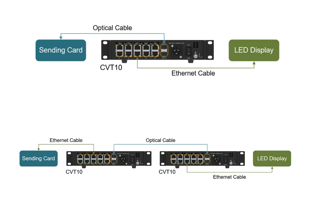
For one compatible optical output group, a sending device with a supported optical output can feed one NovaStar CVT10 at the display end. An Ethernet-only sending system normally needs conversion at both ends of the long fiber span. Larger walls and redundancy schemes can require more devices.
| Source arrangement | Starting quantity | Planning condition |
|---|---|---|
| Compatible controller optical output | One display-side converter | Match optical format, modules, and output mapping |
| Compatible Ethernet-only sending outputs | Two converters | One electrical-to-optical unit and one optical-to-electrical unit |
| Multiple independent output groups | Calculate by group | One converter is not automatically enough for the whole controller |
| Redundant installation | Design-dependent | Account for backup links, sources, power, and failure points |
An optical connector alone does not prove compatibility. Confirm that the controller supports the NovaStar CVT10 transport format and the intended port group. A physically matching LC connection cannot translate between incompatible data protocols.
For example, a project needing sixteen active Ethernet outputs cannot obtain all sixteen from one ten-port converter. If the controller provides two compatible groups of eight, plan and verify a separate receiving-side conversion path for each group. This is a planning example, not a universal wiring instruction for every sixteen-port controller.
Write the group names on the drawing before ordering. Include controller optical-port labels, converter identifiers, Ethernet output numbers, and cabinet destinations. This avoids confusing a backup optical port with a second independent screen feed when equipment arrives on site.
4. NovaStar CVT10 setup and port mapping
01. Connect a supported optical controller
First confirm the controller model, firmware, optical-output mode, and module type. Connect its designated primary optical output to OPT1 on the display-side NovaStar CVT10 using the matching fiber pair. Connect the converter’s assigned Ethernet ports to the receiving-card chains according to the screen connection drawing.
Start with one known-good cabinet or one documented output group. Confirm the source image and cabinet mapping before extending the test across the whole wall. A link indicator can show a physical connection even when the screen configuration is wrong.
02. Connect an Ethernet-only sending system
Use a compatible NovaStar CVT10 near the sending device and a matching unit near the display. Connect the sending outputs to the source-side converter, run the optical link between the converters, and connect the display-side Ethernet outputs to their assigned receiving-card chains. Preserve the documented port order at both ends.
Label both ends of every copper cable and fiber pair. Confirm the primary path first; add the backup path only after the main route works. Do not change controller settings, firmware, fiber polarity, and cabinet mapping simultaneously, because that makes a failed test difficult to diagnose.
03. Understand eight versus ten usable outputs
NovaStar’s current port description distinguishes optical encoding. A 10G upstream connection using 8b/10b encoding makes the first eight Ethernet ports available. A supported 10.3125G connection using 64b/66b encoding makes ten available. In the Ethernet-to-fiber direction, all ten physical Ethernet ports are available.
Therefore, a NovaStar CVT10 with inactive ports nine and ten is not necessarily defective. Check the controller’s optical format before moving cables or seeking a firmware change. Older explanations based only on the sending device’s total Ethernet-port count are less precise than checking the actual optical-output specification.
5. CVT10-S vs CVT10-M: choose fiber and optical modules
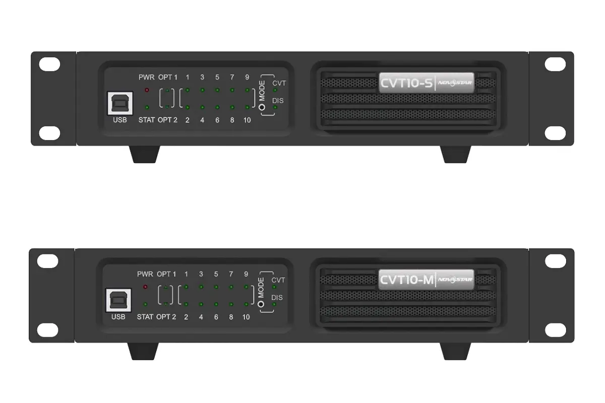
The NovaStar CVT10-S and NovaStar CVT10-M serve the same transport role with different optical arrangements. Select the model against the installed cable plant and required route length, including patch leads and service loops, rather than the straight-line distance between rooms.
| Selection item | CVT10-S | CVT10-M |
|---|---|---|
| Fiber mode | Single-mode | Multimode |
| Rated distance | Up to 10 km | Up to 300 m |
| Wavelength | 1310 nm | 850 nm |
| Specified fiber | OS1/OS2, 9/125 μm | OM3/OM4, 50/125 μm |
| Connection | LC, twin-core | LC, twin-core |
| Typical selection reason | Long route or existing single-mode infrastructure | Suitable shorter route with existing multimode infrastructure |
These are optical-link ratings, not a promise that every cable at the maximum length will work. Connector contamination, damaged fiber, excessive bending, intermediate joints, and optical loss affect the finished link. Have the installed route tested when its condition or loss is uncertain.
Do not pair a stock CVT10-S optical module with a stock CVT10-M module. Match the mode, wavelength, supported module specification, fiber type, and polarity at both ends. A controller with its own optical output needs the same checks even though its chassis does not carry the CVT10 model name.
Order the actual route length with sensible service allowance and appropriate cable protection. For touring, consider how the cable will be reeled, handled, and protected at crossings. For fixed installations, document patch-panel locations and fiber identifiers so a later technician can trace the route without disconnecting unrelated services.
6. NovaStar CVT10 manual, firmware, and NovaLCT
When searching for a NovaStar CVT10 manual PDF, distinguish the converter specification document from the controller manual and the NovaLCT software manual. The converter document explains interfaces and application layouts. The controller manual explains optical-port mapping and supported operating modes. Neither should be replaced by a reseller’s short feature list.
Use the HonghaiLED NovaLCT download and manual list for software resources, then match the package to your hardware. Installing NovaLCT is not the same as upgrading the NovaStar CVT10 firmware. A converter program, a sending-device program, and a receiving-card configuration file perform different jobs.
The documented CVT10 maintenance connection is USB Type-B to a control computer, with NovaLCT V5.4.0 or later specified for program upgrades. The USB port is not a video input or a converter-cascading connection. Use a firmware package explicitly confirmed for the model and revision.
Before maintenance, record the serial number, current versions, controller model, and working topology. Back up the screen connection and receiving-card parameters through the appropriate system software. Arrange stable power and test the complete signal path after any supported upgrade. Do not upgrade a working show system simply because a newer filename appears online.
7. NovaStar CVT10 troubleshooting: isolate the failing stage
Troubleshoot the NovaStar CVT10 in signal-path order: power, optical connection, Ethernet connection, then image configuration. Change one item at a time and record the result. A known-good short fiber lead and a known-good Ethernet lead help distinguish a route problem from an equipment problem.
| Symptom | First check | Next useful action |
|---|---|---|
| No power indication | AC supply, cable, connector, switch | Test the power path before the optical path |
| OPT indication absent | Module match, fiber mode, polarity, connector condition | Test a clean known-good fiber pair |
| Link present, no image | Source output, port group, screen mapping | Test one cabinet with its approved configuration |
| Ports nine and ten inactive | Upstream optical encoding and mapping | Confirm whether the link supports eight or ten outputs |
| Intermittent interruption | Cable movement, bends, connectors, cooling, power | Compare short-link and installed-route operation |
| Only some cabinets fail | Affected Ethernet chain and cabinet power | Trace the first failed cabinet and its incoming connection |
The NovaStar CVT10 indicators help locate a fault but do not certify a correct picture. Normal power and optical indications still leave controller configuration, receiving-card parameters, cabinet order, and source selection to check. If the same cabinets fail on a known-good path, investigate that cabinet chain before replacing the fiber converter.
For a support request, send the topology drawing, clear panel photographs, model labels, software versions, and the exact affected output numbers. Describe whether the problem follows a cable, converter, or cabinet when exchanged. This evidence is more useful than reporting only that the screen is black.
8. CVT10 vs CVT10 Pro and other converter families
The NovaStar CVT10 and CVT10 Pro are separate products. A similar name or port count does not make their mechanical design, environmental protection, power specifications, or supplied accessories interchangeable. Use the exact model’s current documentation for an installation drawing or bill of materials.
If environmental protection is the deciding factor, ask for the applicable ingress-protection rating and the conditions required to maintain it, including connector sealing. Do not infer outdoor suitability from the word “Pro,” and do not apply the Pro’s enclosure claims to a standard NovaStar CVT10.
The same caution applies when comparing CVT4K, CVT320, and newer converter families. Compare the controller’s supported optical protocol, independent output groups, port speed, backup arrangement, and software requirements before comparing price. A converter intended for another control architecture may have familiar connectors without being a suitable replacement.
For a controller-focused reference, see the HonghaiLED MCTRL4K controller guide. Treat such a guide as background for understanding output groups, then verify the exact converter combination against the controller documentation. Avoid purchasing equipment on the assumption that all NovaStar optical products connect identically.
9. Installation, redundancy, and commissioning checklist
A NovaStar CVT10 can place conversion close to a stadium screen, rental wall, or remote display area. The useful design question is where each transport stage belongs. Keep equipment accessible for inspection and provide a route that technicians can identify during a fault.
01. Mount and protect the equipment
Use the mounting arrangement and hardware specified for the supplied unit. Support cables so their weight does not pull on the optical connectors. Keep ventilation openings clear and account for the temperature inside an enclosed rack, which can exceed room temperature. Do not assume the standard converter can sit unprotected beside an outdoor cabinet.
Connect power according to the unit’s instructions. NovaStar warns against making a live PowerCON connection for the connector arrangement described in its CVT10 document. Plan power access before rigging, and keep fiber ends protected when disconnected. Never inspect an active optical output by looking into it.
02. Test the backup as a complete path
OPT2 provides a backup role in the documented NovaStar CVT10 CVT mode. That does not by itself remove every single point of failure. A shared converter, shared power supply, or two fibers in the same vulnerable route may still interrupt both paths.
Commission the actual redundancy design during a controlled test window. Verify the primary picture, deliberately interrupt the intended primary link, observe the result, restore it, and document recovery. Confirm the controller’s backup configuration rather than assuming a second connected cable automatically provides the required protection.
03. Record acceptance results
Check every mapped output and cabinet using suitable test patterns and normal program material. Record the operating mode, source format, port assignments, installed cable lengths, and results of the backup test. Label the equipment consistently with the drawing and leave the working configuration with the project records.
These practical records help the next technician distinguish an expected port limitation from a new fault. They also make a replacement NovaStar CVT10 easier to commission because the required optical mode and port allocation are already known.
10. NovaStar CVT10 price and quotation checklist
A useful NovaStar CVT10 price comparison starts with identical scope. A converter-only listing may exclude the cable route, backup fiber, shipping, or local service needed for your project. No fixed HonghaiLED selling price is stated here because the final configuration and commercial terms need confirmation.
Request a quotation specifying CVT10-S or CVT10-M, quantity, optical-module inclusion, firmware compatibility, mounting accessories, power-cord type, and warranty terms. Add the fiber type, length, connector arrangement, protection method, and any patch-panel requirements. For redundant systems, list the primary and backup items separately.
Provide the controller model, receiving-card model, screen resolution, cabinet layout, and required operating format. Pixel pitch and screen area alone do not establish the number of sending outputs. A complete port plan makes the NovaStar CVT10 quotation easier to compare and reduces the risk of ordering too few converters.
Ask the supplier to identify the hardware documentation used for the quoted units, especially where published power or dimension figures differ. Confirm stock, delivery terms, and technical support directly instead of treating a search-result price as a complete installed-system cost.
11. NovaStar CVT10 frequently asked questions
01. What is the NovaStar CVT10 used for?
The NovaStar CVT10 transports compatible LED display data between electrical and optical connections. It extends the signal path between the sending system and receiving cards. It does not provide the video processing, cabinet mapping, or display-driving functions of the other devices.
02. How far can CVT10-S and CVT10-M transmit?
The specified optical reach is up to 10 km for CVT10-S and up to 300 m for CVT10-M with the matching fiber and modules. The complete installed route must also meet the optical-link requirements; distance alone is not a successful commissioning test.
03. Does every controller with an optical port work?
No. Confirm the supported transport format, optical encoding, module specification, and port mapping. Physical connector compatibility is only one part of the check. Obtain confirmation for the exact controller and firmware before selecting the NovaStar CVT10 arrangement.
04. Why are only eight Ethernet outputs available?
The upstream optical format can limit the active outputs. NovaStar specifies eight outputs for a 10G 8b/10b link and ten for a supported 10.3125G 64b/66b link. Check this before treating ports nine and ten as a hardware fault.
05. Can I mix single-mode and multimode units?
Do not connect the stock single-mode and multimode optical arrangements together. Match both ends to the specified fiber and optics. Substituting a module requires confirmed compatibility; a connector that fits is not enough to establish a supported link.
06. Where is the NovaStar CVT10 firmware connection?
The USB Type-B control connection is used with the appropriate NovaLCT software and confirmed converter program. It is separate from the optical data path. Keep software installation, device firmware, and receiving-card configuration files clearly distinguished during maintenance.
07. Does a second optical cable guarantee redundancy?
No. The backup must be supported and correctly connected throughout the system. Shared power, a common cable route, or a single converter can remain failure points. Test the intended failure scenario before accepting the redundant installation.
08. What should I send for a NovaStar CVT10 quotation?
Send the controller and receiving-card models, screen resolution, cabinet layout, fiber route length and type, output-group plan, and backup requirements. Include the installation environment and destination so the supplied equipment, accessories, and documentation can be checked together.
12. Choose a NovaStar CVT10 from a verified signal plan
Select the NovaStar CVT10 from the controller outward: establish compatible output groups, match the optical mode to the installed fiber, calculate the required converters, and test the complete display path. Use CVT10-S or CVT10-M according to the confirmed optical requirements, then check the supplied unit’s electrical and mechanical documentation.
For help checking a NovaStar CVT10 configuration, contact HonghaiLED with your controller model and cable plan. A clear topology, practical installation details, and documented acceptance tests provide a stronger basis for a reliable LED screen than port count or transmission distance alone.
Technical references reviewed: NovaStar CVT10 Fiber Converter Specifications V1.3.7; NovaStar CVT10 product webpage; NovaStar CVT10 Fiber Converter Specifications V1.3.0 for earlier interface descriptions. Checked October 10, 2026. Published-source disagreements are identified in Section 1; installation examples and purchasing checklists are practical planning guidance, not additional manufacturer specifications.
Related Posts
NovaStar A10s Pro Receiving Card: Specs, Setup & Datasheet
The NovaStar A10s Pro is a compact LED receiving card…
NovaStar MG Series Distributed Processors: 2K vs 4K Guide
NovaStar MG Series distributed processors move video, audio and control…
NovaStar EL2000 Video Wall Splicer: Specifications & Setup
The NovaStar EL2000 is a hardware video wall splicer that…

No Comments