
NovaStar MCTRL300 User Manual, Specs and NovaLCT Setup Guide
The NovaStar MCTRL300 is a synchronous LED display controller with one DVI video input, two Gigabit Ethernet outputs and USB configuration through NovaLCT. Its output budget is up to 1.3 million pixels across two ports, while its supported DVI input can reach 1920 × 1200 at 60 Hz. These are different limits: accepting a large source image does not mean the controller can drive every pixel of that image.
This NovaStar MCTRL300 manual guide covers specifications, software downloads, wiring, receiving-card configuration, price considerations and practical fault isolation. It is written for installers and buyers who need to match a controller to a real cabinet layout, rather than choose by screen dimensions alone.
Quick answer: choose the NovaStar MCTRL300 when you have a compatible DVI source and a verified port allocation. Use an external processor or another controller when the project requires scaling, source switching or greater output capacity. Jump to manual and software downloads or the NovaLCT setup procedure.
1. What is the NovaStar MCTRL300?
The NovaStar MCTRL300 is an external sending controller between a video source and the receiving cards inside an LED wall. Searches for “MCTRL 300,” “MCTRL-300” and “MCTRL300 LED display controller” generally refer to this same model. Receiving cards then distribute the assigned image data to the LED modules.
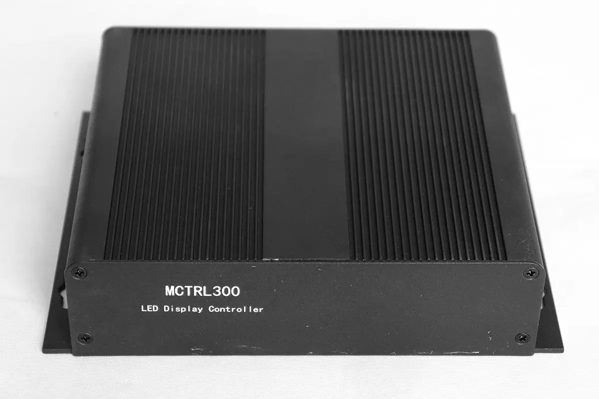
01. NovaStar MCTRL300 signal path
Think of the system as two separate connections. The video source supplies the image through DVI; the configuration PC communicates through USB. A USB connection alone does not carry the live desktop picture. The controller’s RJ45 outputs connect to the LED receiving-card chains, not to a normal office network for web control.
The NovaStar MCTRL300 needs a continuous external video source for synchronous playback. It is not a USB-stick media player. Its light-sensor connector and calibration support can help an appropriately configured system maintain suitable brightness and color uniformity.
02. Where it fits in an LED installation
For an existing wall, identify the receiving-card model, cabinet pixel dimensions and working configuration before replacing the sender. Matching connectors is insufficient evidence of compatibility. For a new rental LED display, plan the data cabling alongside the cabinet layout so a single overloaded output does not limit an otherwise suitable design.
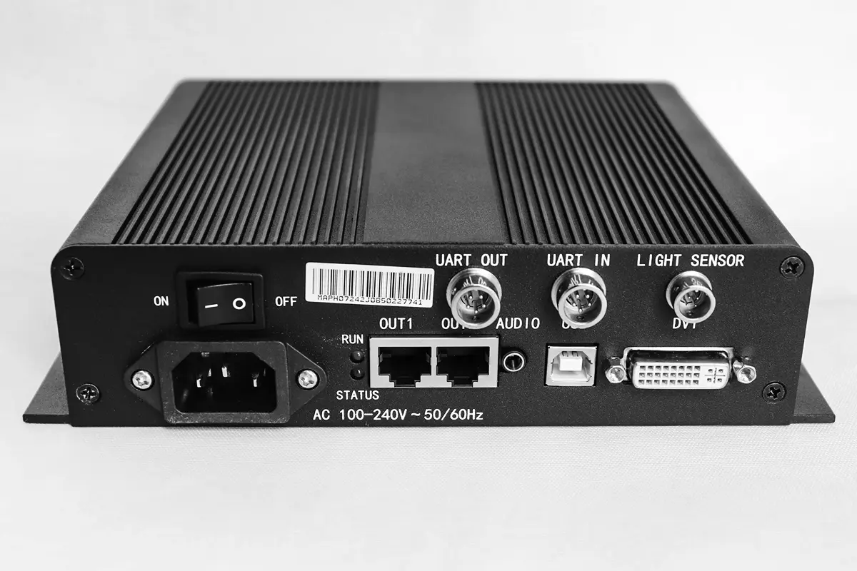
2. NovaStar MCTRL300 specifications
The following NovaStar MCTRL300 specifications use the official V2.4.1 specification sheet, dated August 22, 2024. Older documents and product pages contain different figures, so check the document and firmware applicable to your unit before designing a custom timing.
| Item | Published specification / planning meaning |
|---|---|
| Video | 1 × single-link DVI; 8-bit RGB 4:4:4; progressive input |
| Input timing | Up to 1920 × 1200 at 60 Hz; interlaced signals unsupported |
| Custom input examples | 3840 × 600 at 60 Hz; 548 × 3840 at 60 Hz |
| LED outputs | 2 × Gigabit Ethernet; up to 650,000 pixels per port |
| Configuration | USB Type-B; UART IN/OUT for cascading up to 20 units |
| Other connections | Audio input and light-sensor connector |
| Power | AC 100–240 V, 50/60 Hz; rated consumption 3.0 W |
| Environment | −20°C to +60°C; 10–90% RH, non-condensing |
| Chassis and shipping | 204 × 160 × 48 mm; 1.04 kg; packing box 280 × 217 × 119 mm |
01. Input resolution versus LED output capacity
A 1920 × 1200 input contains 2,304,000 pixels. That exceeds the combined 1,300,000-pixel output budget used for NovaStar MCTRL300 planning. Likewise, the custom input examples do not promise an LED wall of the same dimensions. Confirm both the accepted video timing and the mapped screen area.
Calculate screen pixels as width in pixels multiplied by height in pixels. Then calculate every output chain separately. A 1280 × 720 wall contains 921,600 pixels and passes the total-pixel check, but an uneven split could still place more than 650,000 pixels on one port. Receiver limits, cabinet geometry and the actual signal timing remain separate checks.
02. Worked cabinet allocation
For an illustrative wall of ten cabinets across and six high, with each cabinet measuring 128 × 128 pixels, the screen is 1280 × 768: 983,040 pixels. Assigning thirty cabinets to each output gives 491,520 pixels per port. This passes the published pixel budgets; it is a calculation example, not a guarantee for an unidentified receiving card.
Do not count a backup output as extra independent capacity. If one output must take over the other’s complete chain, the surviving path must accommodate that load. Test the intended redundancy topology on the assembled NovaStar MCTRL300 system.
3. MCTRL300 indicator lights explained
Read the NovaStar MCTRL300 power and operating indicators before changing software settings. They distinguish missing input from several downstream display problems, but a normal input indicator does not prove that the receiving-card mapping is correct.
| Indicator | Observed behavior | Meaning / first check |
|---|---|---|
| RUN, green | One flash every two seconds | Video unavailable; inspect source, DVI cable and timing |
| RUN, green | Four flashes per second | Video available; investigate output mapping if the wall stays black |
| RUN, green | Thirty flashes per second | Startup image is being displayed |
| RUN, green | Breathing | Ethernet redundancy has taken effect |
| STA, red | Continuously lit | Power supply normal |
| STA, red | Off | Power absent or abnormal; check the supply path |
These meanings are specified in NovaStar’s V2.4.1 document. Record the NovaStar MCTRL300 indicator behavior together with the symptom. “Black screen with slow RUN flashing” is a much more useful support report than “controller not working.” When a cable change fixes the input indication but not the picture, continue downstream rather than repeating source adjustments.
4. NovaStar MCTRL300 price
A useful NovaStar MCTRL300 price comparison covers the complete delivered system, not just the sending box. Ask for a dated quotation in your currency, with stock status, accessory list, warranty terms and freight shown separately. Historical listing prices should not be treated as a current offer.
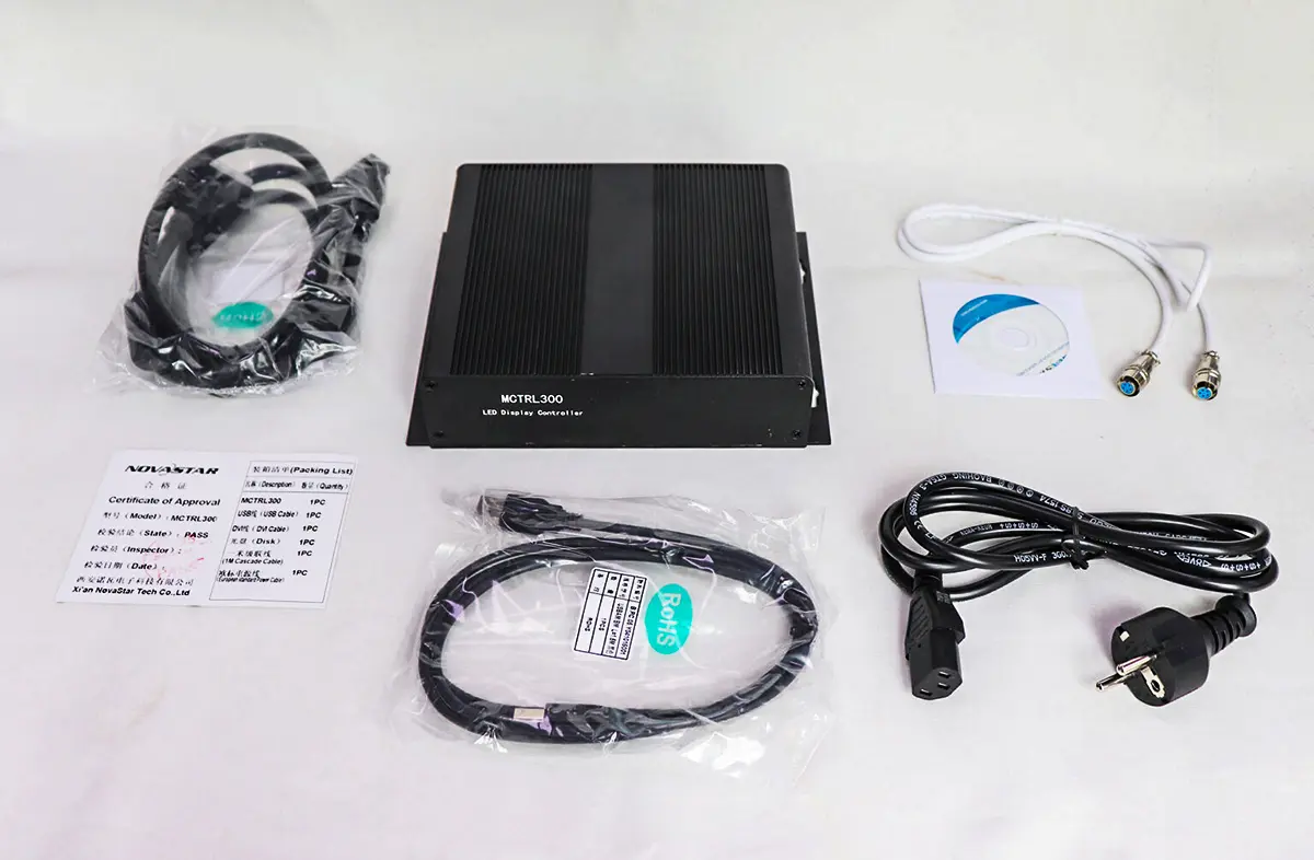
For the NovaStar MCTRL300, the published accessory list includes power, USB and DVI cables plus a one-meter cascading cable. Confirm what the seller actually supplies, particularly for used hardware or replacement-only orders. A missing video adapter, incompatible receiver configuration or extra site visit can cost more than a small difference in controller price.
| Cost item | What to confirm |
|---|---|
| Controller | Exact model, condition, hardware label and supplied firmware |
| Cables and adapters | DVI, USB, power plug, cascading cable and source-adapter requirements |
| Integration | Receiving-card compatibility, cabinet configuration and commissioning support |
| Delivery | Shipping, import charges, delivery terms and lead time |
| After-sales support | Warranty scope, return process, spare availability and support response |
Send your cabinet count, pixel dimensions, receiving-card model, source connection and destination to request an HonghaiLED quotation. This lets the supplier confirm whether the NovaStar MCTRL300 fits before pricing a package.
5. NovaStar MCTRL300 manual, NovaLCT and firmware downloads
Use separate resources for hardware specifications, NovaLCT operation and firmware. A NovaStar MCTRL300 datasheet describes ports and limits; it does not replace the software manual or the cabinet manufacturer’s configuration file.
- MCTRL300 specifications V2.4.1 PDF: official hardware reference, indicators and dimensions.
- NovaLCT synchronous-control user manual V5.3.02 PDF: a documented reference for the sending-card, receiving-card and screen-connection workflow; newer interfaces can differ.
- NovaLCT software downloads and version archive: choose the release recommended for your installed equipment instead of assuming every newer release is suitable.
- Official NovaStar MCTRL300 downloads: check the firmware package and its release notes against your unit before updating.
01. Choose the correct software and configuration file
NovaLCT is the configuration tool used in this guide. The NovaStar MCTRL300 firmware, the NovaLCT installer and a receiving-card configuration are different files with different purposes. A downloaded firmware package will not repair a wrong cabinet scan configuration. Obtain the correct receiving-card file from the panel supplier and retain the original working version.
02. Decide whether a firmware update is necessary
Record the current versions, export the configuration and identify a relevant fix in the release notes. Schedule changes outside show time, use stable power and follow the supplier’s matching instructions. The official product page lists firmware V4.7.12.0.STD when checked for this guide; this is not a blanket upgrade recommendation for every NovaStar MCTRL300 installation.
If a commissioned wall works correctly, preserve its known configuration before experimenting. Keep the approved installer, firmware information, receiving-card files and cabling drawing together so another technician can restore the system without guessing.
6. Step-by-step: how to set up the MCTRL300 with NovaLCT
Prepare the cabinet drawing, receiving-card file and a known-good video source before starting NovaStar MCTRL300 setup. The sequence below is a commissioning checklist. Menu labels vary by NovaLCT release and the functions available in the connected hardware.
01. Install NovaLCT and document the starting point
Use a Windows PC with the supplier-approved NovaLCT installation and required USB driver. Record the wall’s rows, columns, cabinet pixel size, receiving-card models and source timing. On an existing installation, read back and export the working settings before sending replacements. Photograph the cable routes and label each output chain.
02. Connect video, USB and cabinet data paths
Connect the video source to the NovaStar MCTRL300 DVI input and the configuration PC to USB Type-B. Connect each LED output to the correct first receiving card, then follow the planned cabinet chain. Check the power indication after applying power. Keep video and USB roles distinct: successful USB detection does not confirm a valid picture at DVI.
If the source uses HDMI or DisplayPort, verify the specific adapter and output format with the supplier. An adapter does not add scaling, source switching or a native HDMI connector to the controller. Test the source chain before connecting the entire wall so input faults do not become confused with cabinet faults.
03. Confirm communication with the correct controller
Open NovaLCT and select the communication device associated with the connected sender. Confirm that the NovaStar MCTRL300 is detected before editing the wall. If it is absent, check power, the USB data cable and driver recognition, and try a direct PC connection. A screen-configuration window that opens without an attached device is not proof of communication.
04. Configure receiving cards and screen connections
In Screen Configuration, load the panel supplier’s verified receiving-card file. Test a representative cabinet before applying the file across the wall. Pixel pitch alone does not identify the correct file: module scan arrangement, driver ICs and wiring also matter. Avoid trial-and-error changes to these parameters on a working installation.
Next, map the screen connection in the actual cable order. Set each receiver’s pixel width and height, assign the output port and draw the route cabinet by cabinet. Recalculate the load on both NovaStar MCTRL300 outputs. Send the configuration to the intended hardware, then verify a numbered test image across every cabinet rather than relying on a uniform color field.
05. Match the source canvas and displayed area
Choose a progressive source timing supported by the controller and video adapter. Place the intended content within the mapped LED area of that canvas. Check offsets and pixel mapping if only a corner of the desktop appears. The input resolution and physical wall resolution need not be identical, but their relationship must be deliberate.
For example, a 1280 × 768 wall supplied from a larger desktop needs content prepared for that mapped area, or upstream scaling configured to fit it. Enlarging the source resolution alone does not make a low-resolution LED wall display more physical pixels. Use fine text, a border pattern and corner labels to reveal clipping or displacement.
06. Check brightness and color consistency
Start with a comfortable brightness for the venue and inspect red, green, blue, white and grayscale patterns. Compare receiving-card settings and module batches before concluding that calibration is the only cause of a mismatch. The NovaStar MCTRL300 supports pixel calibration with NovaLCT and NovaCLB, but accurate calibration requires appropriate measurement data and a controlled procedure.
Retain existing calibration coefficients unless the panel supplier instructs otherwise. If automatic brightness is used, verify the compatible light sensor and its configured response under realistic ambient conditions. Confirm image quality at the brightness actually intended for operation.
07. Save to hardware, export files and power-cycle test
Sending settings and saving them persistently are separate steps. Use the appropriate Save command after the image is correct, then export the receiving-card and screen/system configuration files. DVS LED’s NovaLCT instructions also distinguish transferring settings from saving them in receiver memory.
Perform a controlled power cycle and confirm that the NovaStar MCTRL300 system returns to the correct picture. Keep a second backup off the configuration PC. Include the cabinet map, software version, brightness settings and source timing; Daktronics’ backup guidance similarly separates receiver, display and system configuration files.

7. MCTRL300 troubleshooting
Diagnose NovaStar MCTRL300 problems in order: power, video input, USB communication, output cabling, receiver configuration and mapping. Change one variable at a time and record whether the symptom follows the source, cable, output or cabinet.
| Symptom | Likely area | Useful next action |
|---|---|---|
| Not detected in NovaLCT | USB communication | Confirm power and driver recognition; test a known-good USB data cable directly to the PC |
| Black wall, slow RUN flashing | Video input | Check source output, DVI connection and a supported progressive timing |
| Black wall, normal RUN flashing | Output path or configuration | Test one known-good cabinet and verify receiver detection, blanking and brightness |
| Repeated or scrambled cabinet images | Receiver file or cable mapping | Restore the supplier-approved cabinet file and compare the map with physical wiring |
| Some cabinets missing | Port load or broken data chain | Calculate each output load; inspect the first failed cabinet and preceding connection |
| Image cut off or wrong size | Canvas and offsets | Check source canvas, mapped area and upstream scaling |
| Brightness or color mismatch | Settings, calibration or hardware | Compare receiver settings and modules before recalibrating |
| Settings lost after restart | Persistent save or reset | Restore backup, save to hardware and repeat a controlled restart |
Factory reset is not a first-line diagnostic step. NovaStar documents a 128 × 128 default screen configuration after reset and a 1080p default resolution after initialization in the V2.4.0 change history. A reset can therefore replace the layout you are trying to recover.
For support, provide the NovaStar MCTRL300 label, NovaLCT version, input timing, cabinet resolution, output allocation, indicator behavior and a photograph of the fault. A short test using one verified cabinet can isolate the sender/source path from faults introduced farther along the chain. Do not promise a firmware fix until the failure has been identified.
8. Is the MCTRL300 the right controller for your screen?
The NovaStar MCTRL300 is a reasonable candidate when the source, pixel budget and receiver ecosystem already match its capabilities. Evaluate the complete signal chain before choosing a replacement or expanding a wall.
| Requirement | Decision |
|---|---|
| One compatible DVI source and modest pixel load | Evaluate the MCTRL300 after checking both output chains |
| A full 1920 × 1080 LED wall | 2,073,600 output pixels exceed the 1.3-million planning budget |
| Several live sources or automatic scaling | Use a suitable video processor or all-in-one controller |
| Remote LAN management or standalone playback | Choose hardware specifically providing the required control/player functions |
| Multiple sending controllers | Plan video distribution, screen regions and control connections separately |
| Redundancy | Validate the backup topology and capacity of each surviving path |
For a higher-capacity sending option, compare the NovaStar MCTRL600 guide. For source switching and processing requirements, review the VX400 Pro guide against your input and output specifications. These are different selection paths, not automatic substitutes for every installation.
UART cascading on the NovaStar MCTRL300 coordinates multiple units; it does not carry the DVI video or merge their outputs into one unlimited port. Each controller still needs an appropriate video feed and mapped region. A larger wall requires an engineered multi-controller arrangement or a suitable higher-capacity system.
9. FAQs about the NovaStar MCTRL300
Select a question to expand the answer. These answers summarize the hardware limits and installation checks discussed above.
01. What is the maximum resolution supported by the NovaStar MCTRL300?
The documented standard DVI input reaches 1920 × 1200 at 60 Hz. V2.4.1 also lists custom input examples of 3840 × 600 and 548 × 3840 at 60 Hz. These are input timings, not a promise to drive a wall containing that many pixels; check output capacity separately.
02. How many pixels can one NovaStar MCTRL300 drive?
Plan for up to 1.3 million pixels across the two outputs, with no more than 650,000 pixels assigned to either port. Verify the receiving-card limits and cabinet allocation as well. A full 1920 × 1080 wall exceeds that total budget.
03. How many NovaStar MCTRL300 controllers can be cascaded?
NovaStar specifies up to 20 units through UART cascading. This is a control connection. Every controller still needs its own valid video feed and screen mapping; adding a UART cable does not distribute video or increase the capacity of an individual Ethernet output.
04. Which software does the NovaStar MCTRL300 use?
Use NovaLCT for configuration from a compatible Windows PC over USB. Keep the software release approved for the installation and obtain the correct receiving-card configuration from the cabinet supplier. NovaLCT configures the system; the live picture still arrives through DVI.
05. Where can I download the manual, NovaLCT and firmware?
Section 5 links the official hardware PDF, a NovaLCT synchronous-control manual, the HonghaiLED software archive and the official product download page. Match firmware to the device and check release notes before installation. Preserve a working backup first.
06. Why does NovaLCT not detect my NovaStar MCTRL300?
Check that the controller has power and that the PC recognizes its USB connection. Test a known-good USB data cable, another PC USB port and the approved driver. Check the selected communication device before changing receiving-card or screen-layout settings.
07. What certifications are listed for the NovaStar MCTRL300?
The V2.4.1 specification lists EAC, CE, FCC, IC, PFOS and CB. Request the documents applicable to the supplied hardware and destination market. A list in a datasheet does not replace verification of the specific product being delivered.
08. How much does the NovaStar MCTRL300 cost?
Request a current, itemized quote covering the controller, accessories, configuration support and delivery. Compare equivalent packages and warranty terms. An old online price or controller-only listing is not a reliable estimate of the complete delivered installation.
09. Does the NovaStar MCTRL300 have HDMI input or built-in scaling?
Its documented video input is single-link DVI. Check any HDMI-to-DVI adapter with the actual source and supported timing. Plan scaling upstream or select a suitable video processor when content must automatically fit a different LED canvas.
10. Conclusion
The NovaStar MCTRL300 works best in a clearly specified system: a compatible DVI source, a correctly mapped LED area, balanced output chains and verified receiving-card settings. Distinguish input resolution from output pixels, test one cabinet before expanding the chain, and save the configuration both to hardware and to backup files.
Use the official specifications and software references above when checking a NovaStar MCTRL300 installation. For a project review, send HonghaiLED your cabinet map and source requirements. The useful result is a documented controller choice, port allocation and recovery procedure that your installation team can reproduce.
Related Posts
NovaStar TB60: Full Introduction and User Manual
The NovaStar TB60 represents the pinnacle of multimedia player technology…
NovaStar VX4S LED Controller: Specs, Setup, Manual and FAQs
Quick answer: The NovaStar VX4S is an all-in-one LED display…
NovaStar VX2000 Pro: Specs, Manual, Price & Downloads
The NovaStar VX2000 Pro is NovaStar’s 20-port all-in-one 4K LED…

No Comments